Refrigerant charge indication

a technology of refrigerant and charge indication, which is applied in the direction of refrigeration machines, lighting and heating apparatus, refrigeration safety arrangements, etc., can solve the problems of reducing system capacity, premature compressor failure, damage to motor and mechanical components

Inactive Publication Date: 2010-04-15
CARRIER CORP
View PDF101 Cites 51 Cited by
  • Summary
  • Abstract
  • Description
  • Claims
  • Application Information

AI Technical Summary

Benefits of technology

[0015]The microprocessor also calculates an average value for the degrees of subcooling over a preselected time period of system operation and outputs an indication of a refrigerant charge status over the preselected time period of system operation. An indicator panel receives a signal from said microprocessor indicative of the refrigerant charge status over the preselected time period of system operation. The indicator panel has a first light adapted to be illuminate for indicating a low refrigerant charge, a second light adapted to be illuminated for indicating a high refrigerant charge, and a third light adapted to be illuminated for indicating a correct refrigerant charge. This information may be used by the non service oriented persons as well as service persons.

Problems solved by technology

Improper charge level, either in deficit or in excess, can cause premature compressor failure.
An over-charge in the system results in compressor flooding, which, in turn, may be damaging to the motor and mechanical components.
Inadequate refrigerant charge can lead to reduced system capacity, thus reducing system efficiency.
Low charge also causes an increase in refrigerant temperature entering the compressor, which may cause thermal over-load of the compressor.
Thermal over-load of the compressor can cause degradation of the motor winding insulation, thereby bringing about premature motor failure.
As operating conditions may vary widely from day to day, the particular amount of cooling measured by the field service technician at any given time may not be truly reflective of the amount of subcooling present during “normal” operation of the system.
Thus, this charging procedure is also an empirical, time-consuming, and a trial-and-error process subject to human error.

Method used


Image

  • Refrigerant charge indication
  • Refrigerant charge indication

Examples


Embodiment Construction

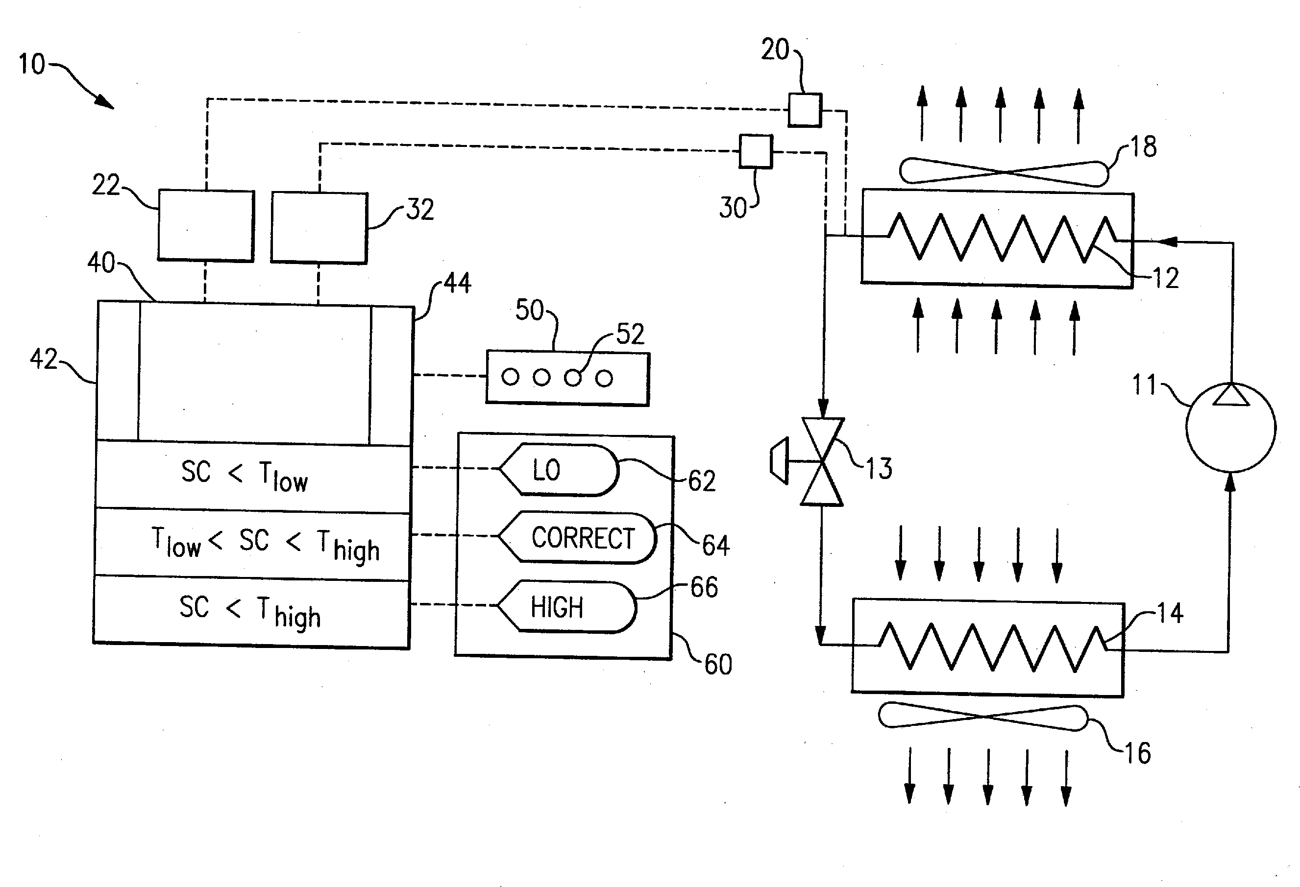
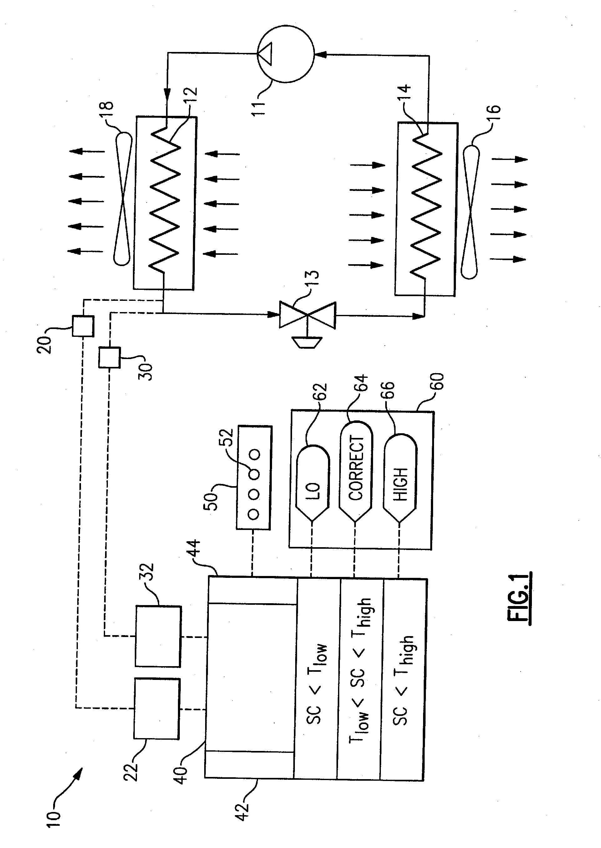
[0018]Referring now to FIG. 1, the invention is shown generally as incorporated into a refrigerant vapor compression air conditioning system 10 having a compressor 11, a condenser coil 12, an expansion device 13 and an evaporator coil 14 connected in serial relationship in refrigerant flow communication in a conventional manner via refrigerant lines forming a refrigerant flow circuit. In operation, the refrigerant, for example R12, R22, R134a, R404A, R410A, R407C, R717, R744 or other compressible fluid, circulating through the refrigerant circuit passes through the evaporator coil 14 in the evaporator in heat exchange relationship with indoor air being passed over the evaporator coil 14 by the evaporator fan 16. As the indoor air passes through the evaporator and over the evaporator coil 14, the refrigerant absorbs the heat in the indoor air passing over the evaporator coil, thereby cooling the air and evaporating the refrigerant. The cooled air is circulated by the fan 16 back into...


PUM


Abstract

A method and apparatus are provided for indicating the status of the refrigerant charge in an air conditioning system based upon the degree of subcooling present in the condensed refrigerant system temperature measurements. The status of the refrigerant charge in the system is indicated in real-time on a service panel for access by a field service technician. The status of the refrigerant charge in the system on a time-average basis for a specified period of operation is presented on an indicator panel. The indicator panel includes a first indicator light indicating that the refrigerant charge is low, a second indicator light indicating that the refrigerant charge is high, and a third indicator light indicating that the refrigerant charge is correct.

Description

BACKGROUND OF THE INVENTION[0001]This invention relates generally to refrigerant vapor compression systems for residential or light commercial air conditioning applications and, more particularly, to a method and apparatus for predicting the refrigerant charge in such systems.[0002]Maintaining proper refrigerant charge level is essential to the safe and efficient operation of an air conditioning system. Improper charge level, either in deficit or in excess, can cause premature compressor failure. An over-charge in the system results in compressor flooding, which, in turn, may be damaging to the motor and mechanical components. Inadequate refrigerant charge can lead to reduced system capacity, thus reducing system efficiency. Low charge also causes an increase in refrigerant temperature entering the compressor, which may cause thermal over-load of the compressor. Thermal over-load of the compressor can cause degradation of the motor winding insulation, thereby bringing about prematur...

Claims


Application Information

Patent Timeline
Patent Type & Authority Applications(United States)
IPC IPC(8): F25B45/00F25B49/00
CPCF25B49/005F25B45/00F25B2345/00F25B2600/05F25B2700/00F25B2700/04
Inventor SCHUSTER, DON A.DAS, SATHISH R.
Owner CARRIER CORP
Why Eureka
Try Eureka