
Signal detector and method employing a coherent accumulation system to correlate non-uniform and disjoint sample segments

a signal detector and accumulation system technology, applied in direction finders using radio waves, navigation instruments, instruments, etc., can solve the problems of limiting the size and occurrence of the sampling period, the signal-to-noise ratio of the received signal b>20/b> over a finite sampling window may not be sufficient to detect the presence and range of satellites, and it is difficult to combine segments of samples captured over different periods of tim

Inactive Publication Date: 2005-02-01
CSR TECH INC
View PDF4 Cites 209 Cited by
  • Summary
  • Abstract
  • Description
  • Claims
  • Application Information

AI Technical Summary

Benefits of technology

The GPS processor directs the signal detector to process each segment of samples. The GPS processor also, responsive to timing signals generated locally by the GPS radio receiver, generates frame marks which are input to the offset measurement circuitry. The offset measurement circuitry determines the offset between the time that a data capture command is issued by the GPS processor and the timing of the next frame mark. This information is provided to the GPS processor for use in determining a carrier phase offset and a code phase offset, so that the correlation results of processing different segments of samples can be coherently combined.

Problems solved by technology

Typically, external constraints limit the size and occurrence of the sampling period.
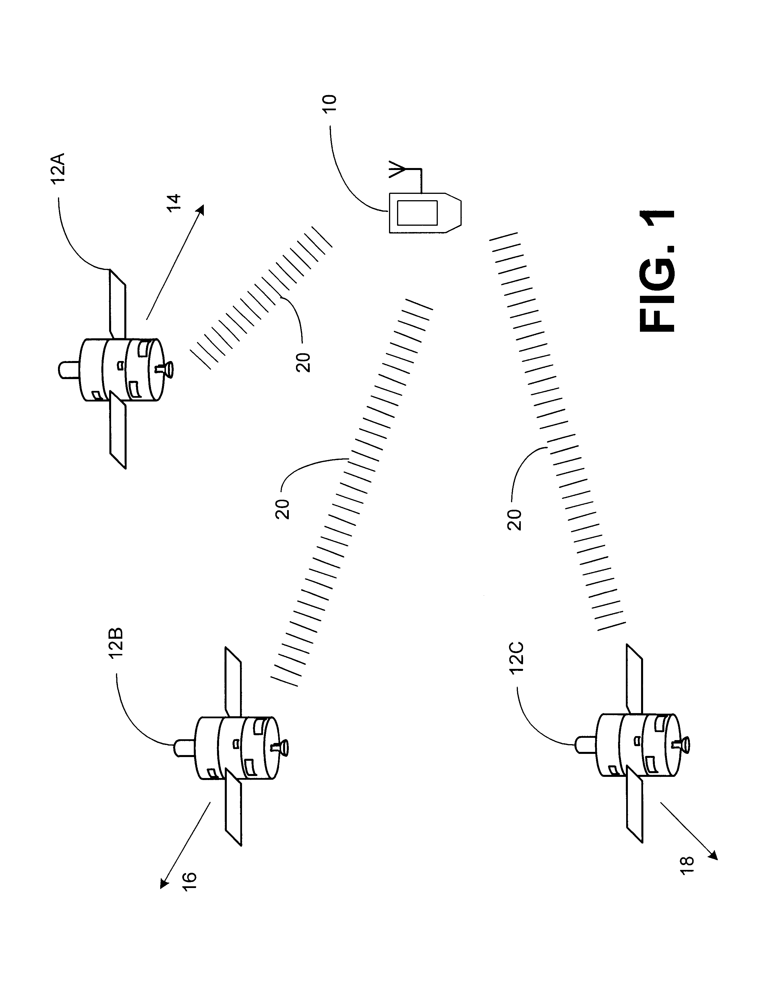
The problem is that the signal-to-noise (S / N) ratio of the received signal 20 over a finite sampling window may not be sufficient to detect the presence and range of the satellites.
Moreover, it is difficult to combine segments of samples captured over different periods of time because each is subject to a different code phase which must be accounted for before the segments can be combined, and these code phases are unknown.
In certain applications, such as the case of a GPS receiver 10 integrated with a mobile wireless phone, extension of the sampling window is not usually feasible since it would subject the received signal to unacceptable interference from the phone's transmitter.
Such occurrences are frequent because of the approximately 11,000 mile distance traveled by the GPS satellite transmissions, because of blockage, multipath fading or attenuation due to buildings, terrain or trees, and because of the noise to a particular satellite represented by the other satellite's transmissions.

Method used


Image

  • Signal detector and method employing a coherent accumulation system to correlate non-uniform and disjoint sample segments
  • Signal detector and method employing a coherent accumulation system to correlate non-uniform and disjoint sample segments
  • Signal detector and method employing a coherent accumulation system to correlate non-uniform and disjoint sample segments

Examples


Embodiment Construction

A. Receiver Having A Signal Detector Employing The Doppler Phase Correction System

1. Architecture

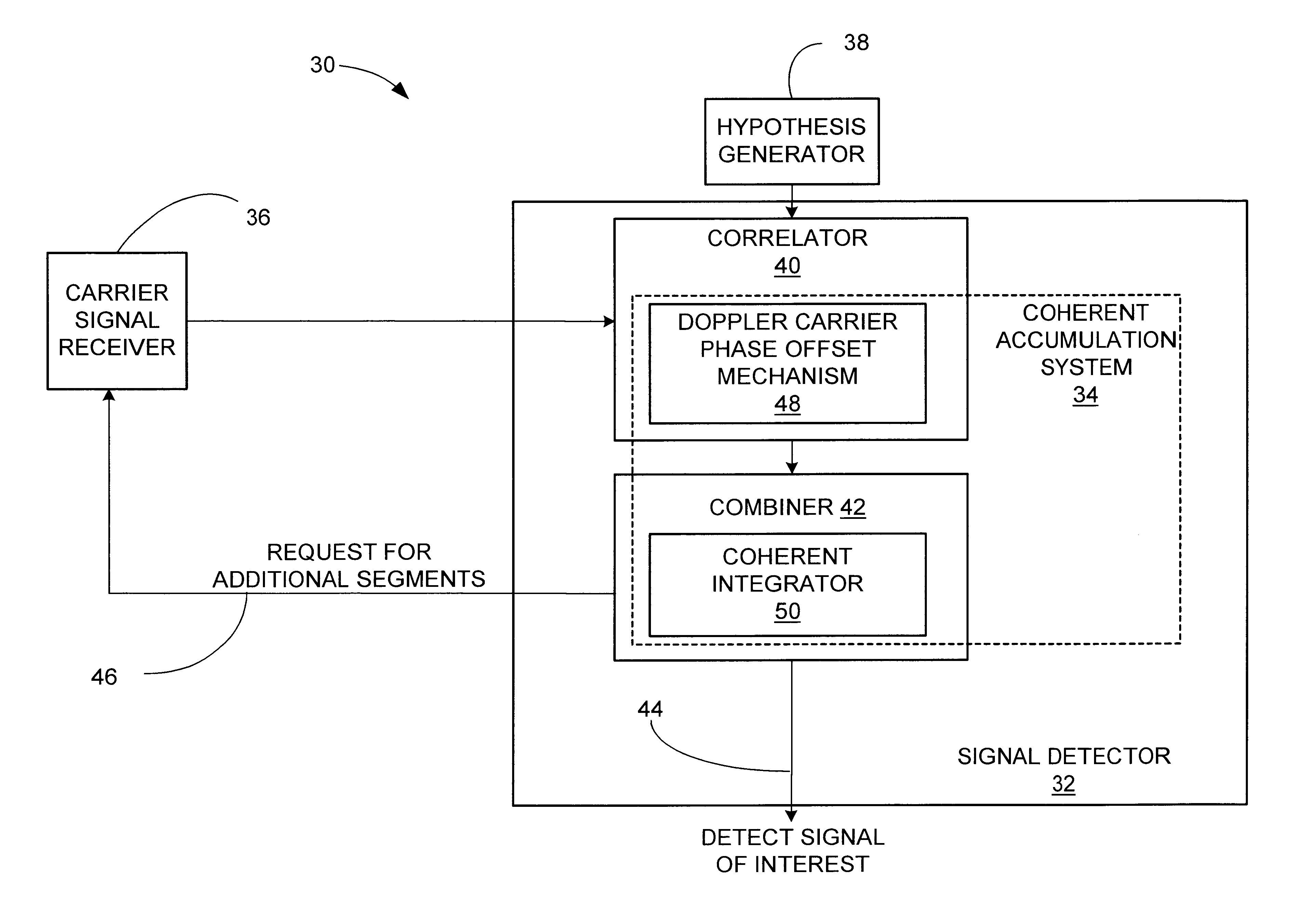
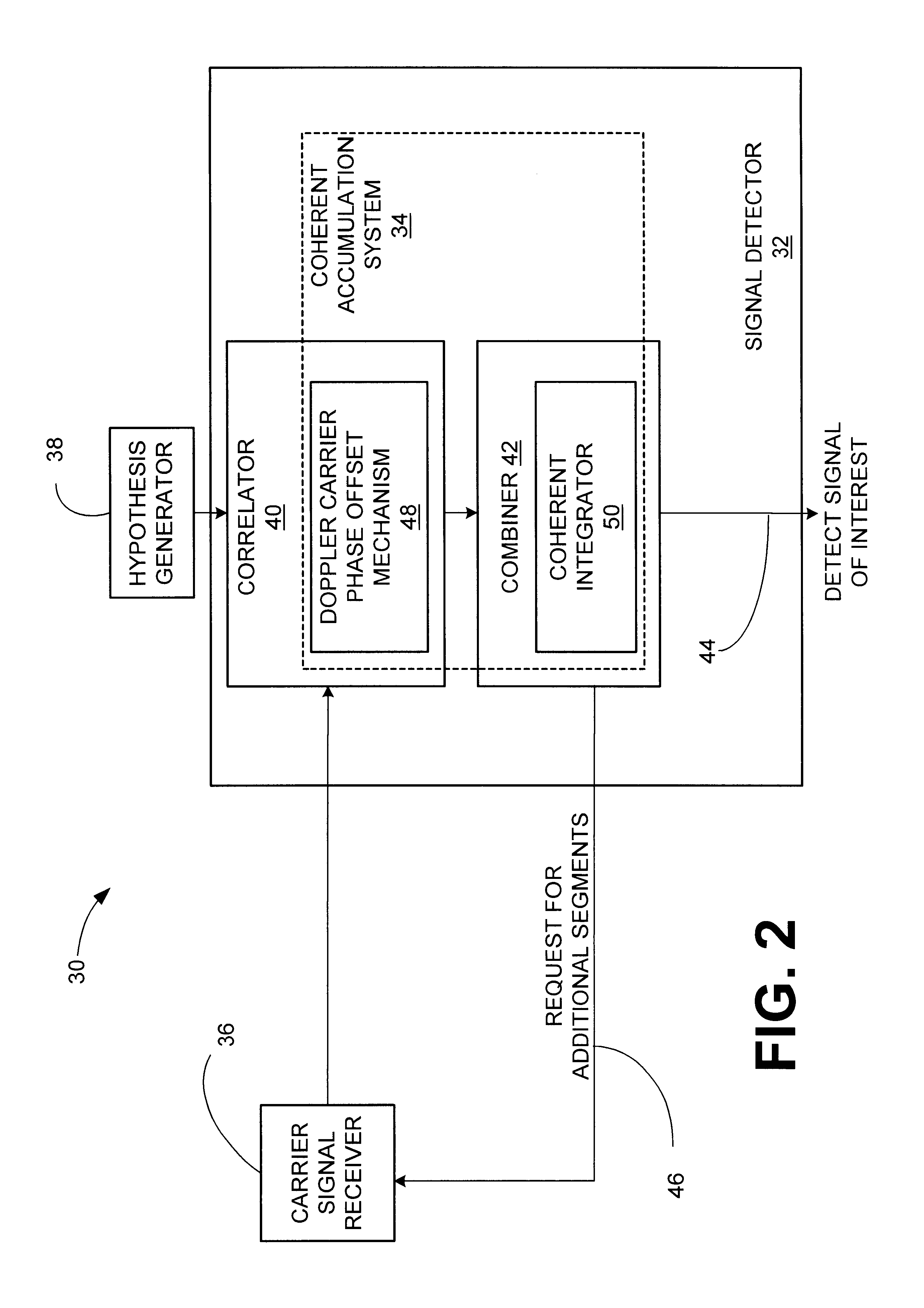
A block diagram of a generalized embodiment (a nonlimiting implementation example) of a receiver 30 that employs a signal detector 32 having the coherent accumulation system 34 in accordance with the subject invention is illustrated in FIG. 2. As illustrated, the receiver 10 comprises a carrier signal receiver 36, for example but not limited to, a conventional radio frequency (RF) receiver, for receiving a carrier signal, continuously or intermittently, encoded with any type of data. Segments of the signal are acquired, and the segments of the signal may be of non-uniform-length and may be disjoint and separated by arbitrary periods of time. The signal may comprise a signal of interest perturbed by noise or pseudo-noise. As an example, in accordance with a spread spectrum modulated signal, the signal may comprise the combination of multiple signals of interest each encoded using one of a...


PUM


Abstract

A signal detector employs a coherent accumulation system that coherently combines the correlation results derived from segments of samples of a received signal. The segments may have non-uniform lengths and may have been obtained over different and non-overlapping time periods. The segments are obtained during sampling windows of arbitrary length and at arbitrary times, and the results of processing the segments are successively combined in a coherent manner (separate magnitude and phase accumulation) until a threshold signal-to-noise ratio (SNR) has been achieved. Coherent integration is enabled by introducing a carrier phase offset as well as a code phase offset, so that different segments are aligned in carrier phase as well as code phase. Although not limited to this application, in one implementation example, the signal detector is used in connection with and as part of a global positioning system (GPS) receiver.

Description

TECHNICAL FIELDThis invention relates to the field of signal detection using correlation analysis, and more specifically, to correlation analysis in which the results of analyzing segments of samples separated in time and possibly having non-uniform lengths are coherently combined to achieve a greater effective signal-to-noise ratio (SNR).BACKGROUND OF THE INVENTIONThe NAVSTAR global positioning system (GPS) is a collection of 24 earth-orbiting satellites. Each of these GPS satellites travels in a precise orbit about 11,000 miles above the earth's surface. A GPS receiver locks onto at least 3 of the satellites, and responsive, thereto, is able to determine its precise location. Each satellite transmits a signal modulated with a unique pseudo-noise (PN) code. Each PN code comprises a sequence of 1023 chips that are repeated every millisecond consistent with a chip rate of 1.023 MHz. Each satellite transmits at the same frequency. For civil applications, the frequency is known as L1 a...

Claims


Application Information

Patent Timeline
Patent Type & Authority Patents(United States)
IPC IPC(8): G01S1/00H04B1/707H04L27/00G01S19/24G01S19/37H04B7/01
CPCG01S19/235G01S19/30H04B1/707G01S19/29G01S19/254G01S19/256H04L2027/0034
Inventor GRONEMEYER, STEVEN A.
Owner CSR TECH INC
Learn More