Lock apparatus and method of use

Inactive Publication Date: 2010-04-15
SECURE STORAGE TECH
View PDF1 Cites 22 Cited by
  • Summary
  • Abstract
  • Description
  • Claims
  • Application Information

AI Technical Summary

Benefits of technology

[0017]In various embodiments, a tether may be associated with the lock assembly. In some embodiments, the tether may be provided with opposite end portions, with one end being secured with either the lock assembly or an adjacent structure, such as the support member. In at least one embodiment, the opposite end portion of the tether will be selectively securable with either a portion of the lock assembly or an adjacent structure, such as the support member. It is contemplated that the tether may be comprised of a rigid cable of durable material, such as braided steel and the like. However, in other embodiments, an electrical line may be disposed to run the length of the tether that is coupled with a power supply to the lock apparatus. The electrical line may further be electrically coupled with one or more processors associated with the lock apparatus. In such arrangements, the processor may be provided with software that is capable of reading a current or “open line” condition of the electrical line. The software may be provided to relay an alarm warning where power is no longer provided to the electrical line within the tether or that the electrical line within the tether has been severed. It is contemplated that the tether may be provided with a length that allows users to easily secure separate articles therewith. In some embodiments, users may secure bike helmets, bike seats, wheels, and the like thereto.
[0018]In some embodiments, a pay point may be associated with the lock apparatus. In particular embodiments, the pay point provides users with an input device, to receive data from the user, and a display for presenting information and feedback to the user. In still other embodiments, the pay point may include an electromagnetic card reader and associated sensors to enable the pay point to read the magnetic strips commonly found on credit cards, ID cards, proprietary cards, and the like. In some embodiments, software may be associated with the processor to determine that a particular validated identification is received from a user. In some instances, the validation may come in the form of a payment from a creditor debit card. In other instances, the validation may come from a proprietary card associated with an operator of the lock ap

Problems solved by technology

Moreover, this Summary is not intended for use as an aid

Method used


Image

  • Lock apparatus and method of use
  • Lock apparatus and method of use
  • Lock apparatus and method of use

Examples


Embodiment Construction

[0041]Embodiments are described more fully below with reference to the accompanying figures, which form a part hereof and show, by way of illustration, specific exemplary embodiments. These embodiments are disclosed in sufficient detail to enable those skilled in the art to practice the invention. However, embodiments may be implemented in many different forms and should not be construed as being limited to the embodiments set forth herein. The following detailed description is, therefore, not to be taken in a limiting sense.

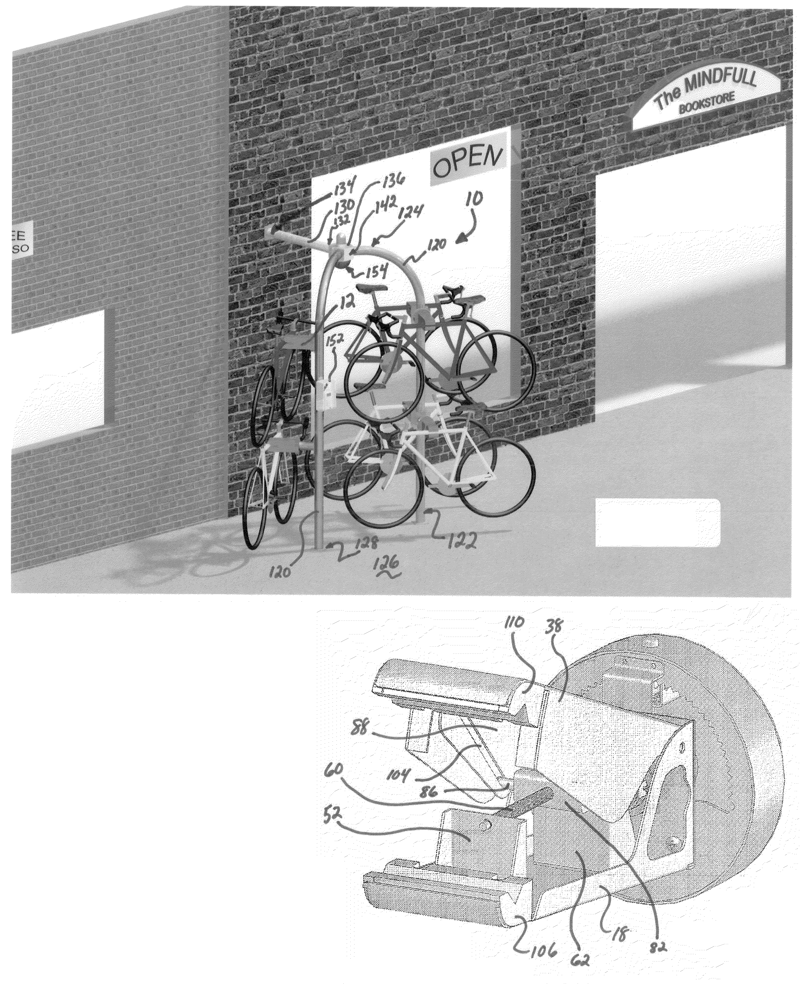
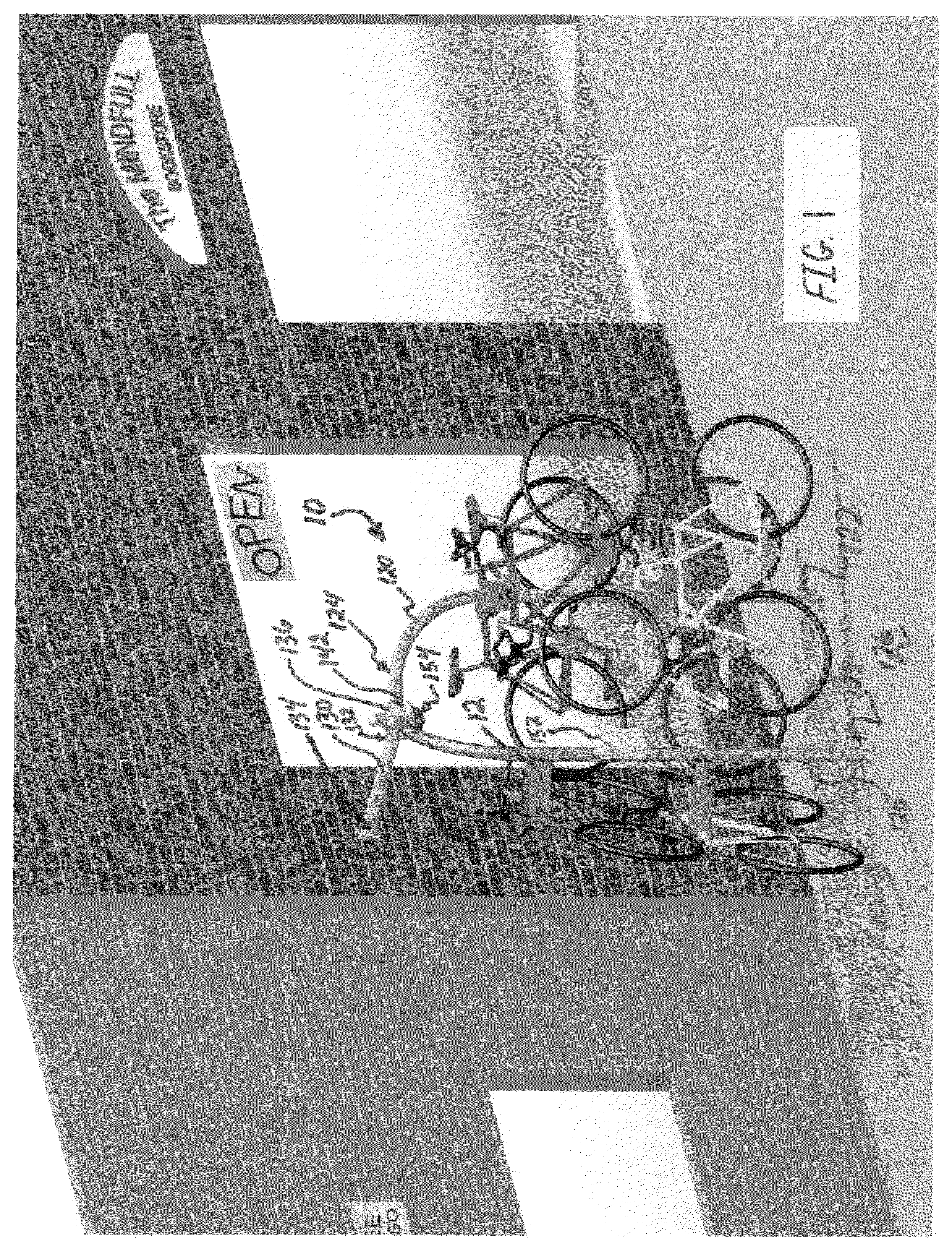
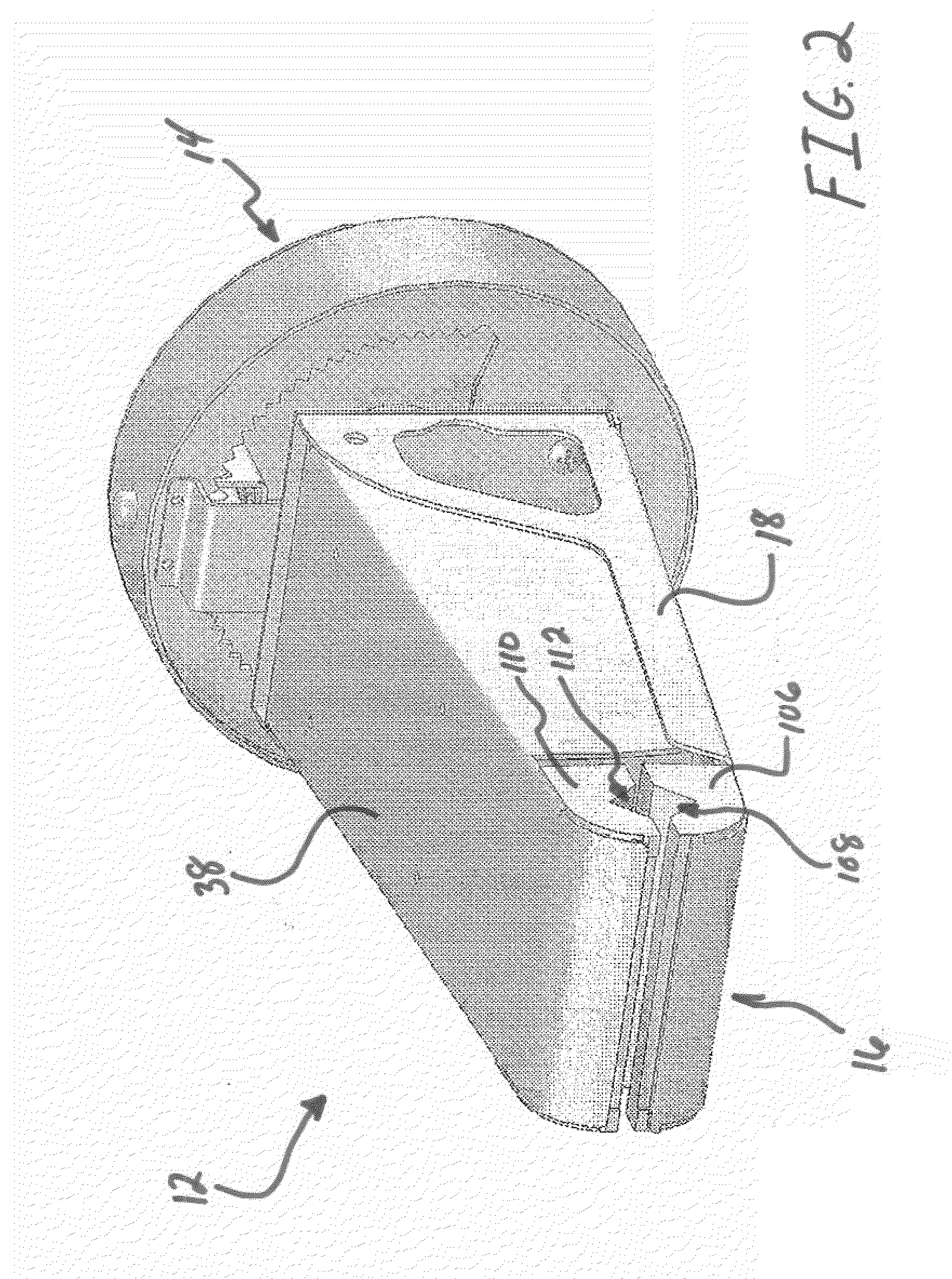
[0042]A lock apparatus 10 and methods of using and fabricating the same are disclosed herein. Generally speaking, the lock apparatus will provide users with storage and security options for a wide array of various articles that may include cycles, skis, fishing tackle, rifles, shotguns, and the like. However, for simplicity of description, examples of the lock apparatus 10 will be described herein as being used to secure and store cycles.

[0043]In various embodim...


PUM


Abstract

Embodiments of a lock apparatus for securing an article, such as a cycle frame, and methods of use of a lock apparatus are presented.

Description

PRIORITY STATEMENT[0001]The present application claims priority to U.S. Provisional Application No. 61 / 051,617, filed May 8, 2008 entitled LOCK APPARATUS AND METHOD OF USE, to U.S. Provisional Application No. 61 / 170,523, filed Apr. 17, 2009 entitled LOCK APPARATUS, METHOD OF USE AND PARKING MANAGEMENT SYSTEM. The contents of these applications and U.S. patent application Ser. No. 11 / 661,545, PCT Number PCT / US05 / 31392, filed Sep. 1, 2005 entitled LOCK APPARATUS AND METHOD OF USE are incorporated herein by reference.BACKGROUND[0002]Bicycle theft, and other types of cycle theft, have long presented very significant and widely recognized problems. These problems arise not only when cycles are in use but also when in storage or during transport of cycles from one place to another.[0003]Common cycle locking apparatus include padlocks, chains, wirelocks, and U-locks. These types of locking apparatus are typically portable and secure a portion of a cycle, such as a wheel or the frame, to an...

Claims


Application Information

Patent Timeline
IPC IPC(8): E05B49/00B62H5/00G07F5/00
CPCG07F17/10B62H3/02Y10T70/5876Y10T70/7102
Inventor DUTT, KANESUNDERMAN, JEFFREY S.WERTZ, KEITHSANGUINETTI, BRUCEJOHNSON, MIKE
Owner SECURE STORAGE TECH
Why Eureka
Try Eureka