Solar array mounting system

a solar array and mounting system technology, applied in the direction of solar heat collector mounting/support, solar heat collector safety, light and heating apparatus, etc., can solve the problems of increasing the cost of photovoltaic solar panels with other types of energy generation, increasing the cost of photovoltaic solar panels, or both

Inactive Publication Date: 2010-04-15
SUNLINK
View PDF29 Cites 118 Cited by
  • Summary
  • Abstract
  • Description
  • Claims
  • Application Information

AI Technical Summary

Benefits of technology

[0013]In general, the present invention is a solar array mounting system having unique installation and grounding features, and which is adaptable for mounting solar panels having mounting holes located in different locations. The solar array mounting system includes tilt brackets and longitudinal links forming columns. A tilt bracket includes a tilt arm for suppor

Problems solved by technology

With the continual rise in conventional energy costs, photovoltaic solar panels (“PV panels”) are increasingly becoming cost competitive with other types of energy generation.
However, such large solar arrays require a sufficiently strong support structure to support not only the weight of the array, but to also provide sufficient resistance to wind forces.
Tightly spaced panels effectively form a large surface area, which could result in damage to the panels, the support structure, or both, under strong wind conditions.
Standing loads are the result of the combined weight of the solar panels and the mounting system.
Other potential environmental hazards include seismic events, temperature extremes, debris and mold.
The most common and problematic forces are wind-related forces (including hurricanes and tornados), namely lift and drag forces generated by the wind conditions.
While non-tilted solar panels do present a lower profile with respect to wind forces, they are less efficient at converting solar energy to electrical energy when install

Method used


Image

  • Solar array mounting system
  • Solar array mounting system
  • Solar array mounting system

Examples


first embodiment

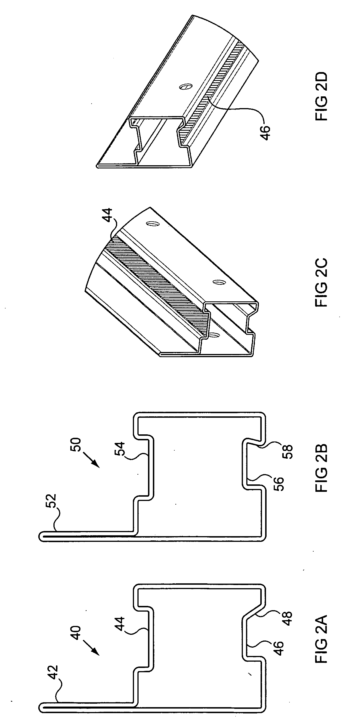
[0060]FIGS. 2A-2D illustrate the construction of the spars in greater detail. In a preferred embodiment, the spars are roll formed from 1 / 16″ steel. In an alternate embodiment the spars can be made from extruded aluminum. The length of a spar is determined by the number of solar panels used in an installation for the module assembly, but is typically between 12-24 feet. illustrated in cross-section in FIG. 2A, a spar 40 has a generally rectangular hollow body (illustrated as a generally square cross-section), with a top channel 44 and a bottom channel 46. Along one edge, the metal is folded back on itself to form an extended section 42. The extended section 42 abuts the edges of the solar panel frames. The front edge 48 of the bottom channel is angled at less than 90° from vertical to facilitate the engagement of a clamp (described below). A perspective view of this embodiment is shown in FIG. 2C.

second embodiment

[0061]a spar is shown in FIG. 2B. It has a similar construction as the spar of FIG. 2A, except that its front edge 58 of its bottom channel 56 angles away from the front edge of the spar 50. This edge 58 facilitates the engagement of a second clamp embodiment (described below).

[0062]For installed solar array systems, it is important to have a common “equipment ground” i.e. to insure that all the metal surfaces are at a common electrical ground reference. For mounting systems made entirely of aluminum or stainless steel, an equipment ground may be easily obtained since all the surfaces are conductive. As long as each component of the system is securely fastened to the other components, a good equipment ground can be obtained. In addition, most photovoltaic solar panels are manufactured with an aluminum frame around the panel. The frame includes mounting holes on the rear side of the panel for mounting the panel to a support structure. Thus, attaching the aluminum frames to a conducti...


PUM


Abstract

A solar array mounting system having unique installation and grounding features, and which is adaptable for mounting solar panels having mounting holes located in different locations. The solar array mounting system includes tilt brackets and longitudinal links forming columns. A tilt bracket includes a tilt arm for supporting an upper spar of one row, and a pivot block for supporting a lower spar of a next row. The spars may be made from extruded aluminum or from steel, wherein the steel spars include an exposed metal channel to provide a common electrical equipment ground. Panel clamps are used to clamp the solar panel frames to the spars, allowing for variations in mounting hole locations.

Description

CROSS REFERENCE TO RELATED APPLICATION[0001]The present application is related to U.S. patent application Ser. No. 11 / 176,036, entitled SOLAR ARRAY INTEGRATION SYSTEM AND METHODS THEREFOR, filed Jul. 7, 2005, the disclosure of which is herein incorporated by reference.BACKGROUND OF THE INVENTION[0002]1. Field of the Invention[0003]The present invention relates generally to a system for mounting and installing photovoltaic solar panels, and more particularly, to a photovoltaic solar panel mounting support system providing enhanced features.[0004]2. Description of the Related Art[0005]With the continual rise in conventional energy costs, photovoltaic solar panels (“PV panels”) are increasingly becoming cost competitive with other types of energy generation. These PV panel systems are being installed in sites of high energy usage, such as on commercial building rooftops, in industrial open areas, and in proximity to substations tied to the electric grid. These commercial energy systems...

Claims


Application Information

Patent Timeline
IPC IPC(8): F24J2/46
CPCF24J2/4638F24J2/5239F24J2/5243F24J2/5254F24J2/5256H02S20/00F24J2002/4661F24J2002/5215Y02B10/20Y02E10/47Y02E10/50F24J2/5264F24S25/16F24S25/60F24S25/632F24S25/634F24S25/70F24S40/85F24S2025/6002F24S2025/6003F24S2025/801H02S20/24Y02B10/10
Inventor MIROS, ROBERT H.J.BIRMINGHAM, MARGARET
Owner SUNLINK
Why Eureka
Try Eureka