Vehicle heat exchangers having shielding channels

a technology of heat exchanger and shielding channel, which is applied in the direction of indirect heat exchanger, heat exchange apparatus safety devices, lighting and heating apparatus, etc., can solve the problems of affecting the resistance of the heat exchanger, the fluid flowing through the broken tube can be leaking more than is desirable, and the cost of implementing the protection screen can be more than desirable, so as to reduce the cost and weight, the effect of improving the resistance to leakage and cost-effectiveness

Inactive Publication Date: 2010-04-15
GM GLOBAL TECH OPERATIONS LLC
View PDF10 Cites 17 Cited by
  • Summary
  • Abstract
  • Description
  • Claims
  • Application Information

AI Technical Summary

Benefits of technology

[0003]An embodiment contemplates a shielded heat exchanger for use in a vehicle. The shielded heat exchanger may comprise a pair of spaced apart headers configured to contain a fluid flowing through the shielded heat exchanger, and a shielded tube. The shielded tube extends between the pair of headers and has a front edge. The shielded tube also includes a flowing channel that operatively engages the headers for fluid flow through the flowing channel between the headers, and a shielding channel extending parallel to the flowing channel between the headers along the front edge of the shielding tube, with the shielding channel configured to prevent flow of the fluid from the headers into the shielding channel.
[0004]An embodiment contemplates a method of protecting a tube of a heat exchanger mounted near a front of a vehicle from leakage due to impacts with objects, the method comprising the steps of: providing a flowing channel in the tube in fluid communication between a pair of headers, and a shielding channel extending adjacent to the flowing channel along a front of the tube; flowing a fluid through the flowing channel between the headers; and blocking any flow of fluid from the headers into the shielding channel.
[0005]An advantage of an embodiment is that the shielded heat exchanger is much less likely to suffer tube leaks due to impacts from objects, such as stones. The shielding channels can absorb the energy of a stone impact, thus shielding the flowing channels from the impact. And, it does not matter if the material of a shielding channel is pierced since it does not carry any fluid through it. The improvement in resistance to leakage due to impacts is also generally more cost effective than employing protection screens. Moreover, shielding channels can be selectively used on the tubes of the heat exchanger that are more likely to receive impacts from objects and not used on tubes that are less likely to receive impacts, thus minimizing cost and weight.

Problems solved by technology

This makes them vulnerable to impacts from objects, such as stones.
The impacts can break one or more of the tubes in the heat exchanger, leading to leakage of the fluid flowing through the broken tube.
But implementing protection screens for the heat exchangers can cost more than is desirable and may reduce the heat exchanger performance somewhat due to a negative effect on the air pressure drop for air flowing through the heat exchanger.
But channels with fluid flowing in them are still exposed, so an impact that pierces the outer wall of this thicker front channel still results in leakage of the fluid flowing through the heat exchanger.

Method used


Image

  • Vehicle heat exchangers having shielding channels
  • Vehicle heat exchangers having shielding channels
  • Vehicle heat exchangers having shielding channels

Examples


first embodiment

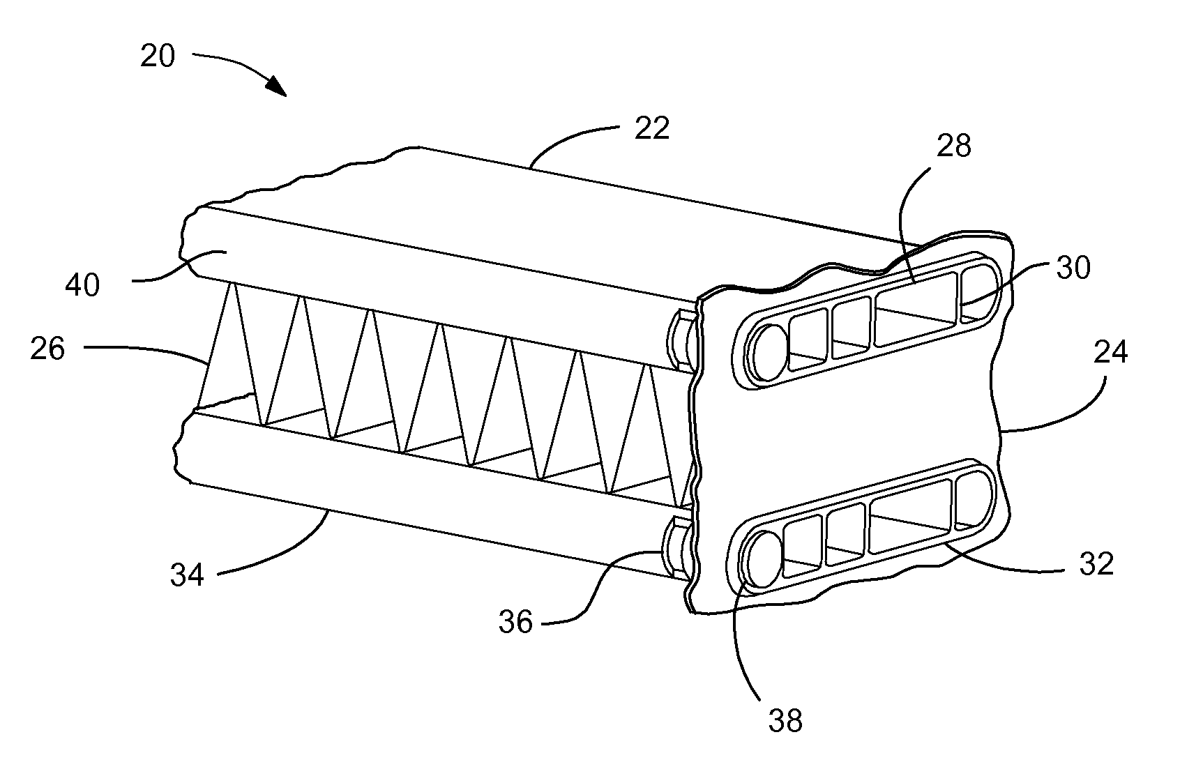
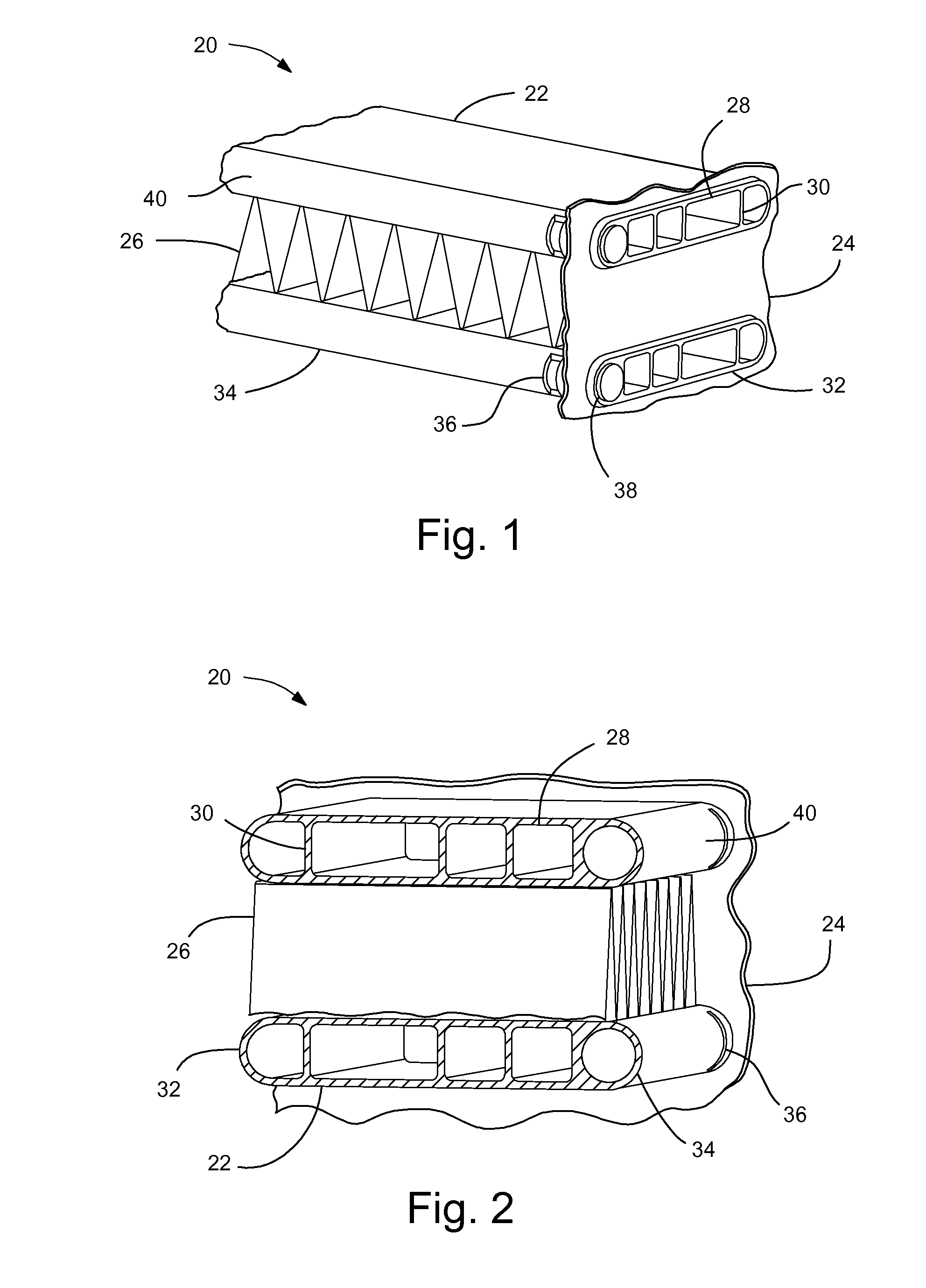
[0015]Both tubes 22 shown in the first embodiment are shielded tubes—that is, the tubes 22 both also include a shielding channel 34 extending across the front 40 of the heat exchanger 20 between the headers 24. The front 40 of the heat exchanger 20 is the side of the heat exchanger 20 that will face toward the front of the vehicle in which it will be used. The shielding channels 34 are, of course, located along the front of the tubes 22 because this is the most likely location for a significant impact from an object, such as a stone, while operating the vehicle.

[0016]Each end of each shielding channel 34 includes a plug 38. The plugs 38 seal the ends to prevent fluid in the headers 24 from entering the shielding channels and leaking out of the heat exchanger 20. The plugs 38 may by made of wire with cladding on it so that the plugs 38 will be welded to the ends of the shielding channels 34 during a brazing process the heat exchanger 20 undergoes during assembly. Of course, other typ...

second embodiment

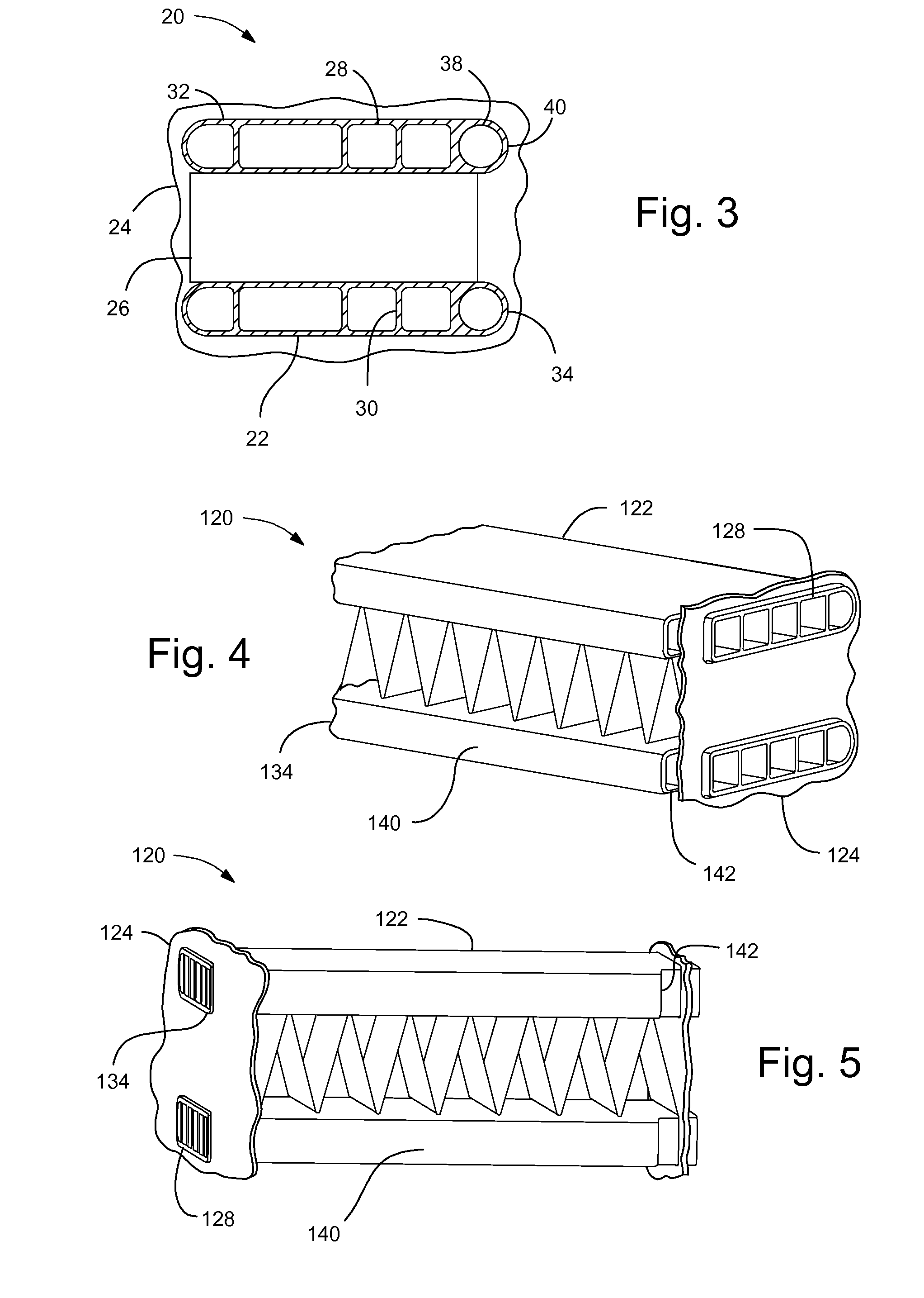
[0021]FIGS. 4-5 illustrate the shielded heat exchanger 120. Since this embodiment is similar to the first, similar element numbers will be used for similar elements, but employing 100-series numbers.

[0022]In this embodiment, the shielding channels 134 at the front 140 of each tube 122 extend almost all of the way across between the headers 124, but stop just short, at open channel ends 142. Thus, while the flowing channels 128 still extend to and direct fluid between the headers 124, the shielding channels 134 do not contact or extend into the headers 124. With this configuration, no brazing or other means of sealing needs to take place to assure that fluids do not leak from the headers 124 into the shielding channels 134.

[0023]In addition, the cross sectional shape of the shielding channels 134 can be whatever is desirable to provide the most advantageous combination of ability to absorb impact energy while minimizing manufacturing costs. This flexibility in cross sectional shape i...

third embodiment

[0024]FIGS. 6-7 illustrate the shielded heat exchanger 220. Since this embodiment is similar to the first, similar element numbers will be used for similar elements, but employing 200-series numbers.

[0025]In this embodiment, one of the tubes is a shielded tube 222 while the other tube is a non-shielded tube 244, with of course a row of fins 226 between them. Thus, there may be a zone 246 of shielded tubes 222 and a zone 248 of non-shielded tubes 244. This illustrates that not all of the tubes need to be shielded tubes. It may be preferable for a particular vehicle application to have only a few of the lowest tubes on the heat exchanger be shielded to provide protection from projectiles while the upper tubes are non-shielded to save weight and cost. Of course, this is applicable to the other embodiments as well.

[0026]For the shielded tube 222, the flowing channels 228 are open to the headers 224 while the shielding channel 234 has welded ends 238 that block fluid flow into this chann...


PUM

PropertyMeasurementUnit
air pressure dropaaaaaaaaaa
thicknessaaaaaaaaaa
energyaaaaaaaaaa

Abstract

A shielded heat exchanger and method of use in a vehicle is disclosed. The shielded heat exchanger may comprise a pair of spaced apart headers configured to contain a fluid flowing through the shielded heat exchanger, and a shielded tube. The shielded tube extends between the pair of headers and has a front edge. The shielded tube includes a flowing channel that operatively engages the headers for fluid flow through the flowing channel between the headers and a shielding channel extending parallel to the flowing channel between the headers along the front edge of the shielding tube, with the shielding channel configured to prevent flow of the fluid from the headers into the shielding channel.

Description

BACKGROUND OF INVENTION[0001]The present invention relates generally to heat exchangers mounted near the front of a vehicle, and more particularly to protection for the heat exchangers from impacts, such as stones, hitting the front of the heat exchangers.[0002]Heat exchangers, such as condensers and radiators, are often mounted near the front of a vehicle in order to assure adequate air flow through them. This makes them vulnerable to impacts from objects, such as stones. The impacts can break one or more of the tubes in the heat exchanger, leading to leakage of the fluid flowing through the broken tube. As a result, some vehicles (particularly off-road vehicles) include protection screens that are mounted to block objects before they can impact the heat exchanger. But implementing protection screens for the heat exchangers can cost more than is desirable and may reduce the heat exchanger performance somewhat due to a negative effect on the air pressure drop for air flowing through...

Claims


Application Information

Patent Timeline
Patent Type & Authority Applications(United States)
IPC IPC(8): B60H1/00F28F9/02B21D53/08
CPCB21D53/08Y10T29/49361F28D1/05383F28F1/022F28F19/00F28F2265/00
Inventor PEREZ, TITO G.CORTES, JULIO A.
Owner GM GLOBAL TECH OPERATIONS LLC
Why Eureka
Try Eureka