Method of manufacturing cards comprising at least one electronic module, assembly produced during this method and intermediate products

a technology of electronic modules and manufacturing methods, applied in the field of manufacturing cards, can solve the problems of not being able to integrate a relatively large electronic module, not being able to disclose the maintenance of the transponder, and generally requiring relatively large batteries or powering

Active Publication Date: 2010-04-15
NAGRAVISION SA
View PDF15 Cites 4 Cited by
  • Summary
  • Abstract
  • Description
  • Claims
  • Application Information

AI Technical Summary

Benefits of technology

[0021]According to a particular feature of the method described above, the resin is spread out using at least one roller or one blade, which moves relative to the plate-electronic module assembly. An intermediate product or card with more or less flat outer surfaces is thus obtained.

Problems solved by technology

Such cards generally require relatively large batteries or powering means of the photovoltaic cell type.
It is not easy to integrate a relatively large electronic module, made up of various elements of variable shape and size, in a card.
Indeed, this document does not disclose how to maintain the transponder in a precise, determined position inside the aperture of the positioning frame.
However, manufacturing tolerances must be taken into account, so that it is difficult to envisage too tight a fit.
There is a further problem in addition to this problem of positioning the electronic module relative to the external contour of the card.
This problem concerns introducing the electronic module within the card manufacturing installation.

Method used


Image

  • Method of manufacturing cards comprising at least one electronic module, assembly produced during this method and intermediate products
  • Method of manufacturing cards comprising at least one electronic module, assembly produced during this method and intermediate products
  • Method of manufacturing cards comprising at least one electronic module, assembly produced during this method and intermediate products

Examples


first embodiment

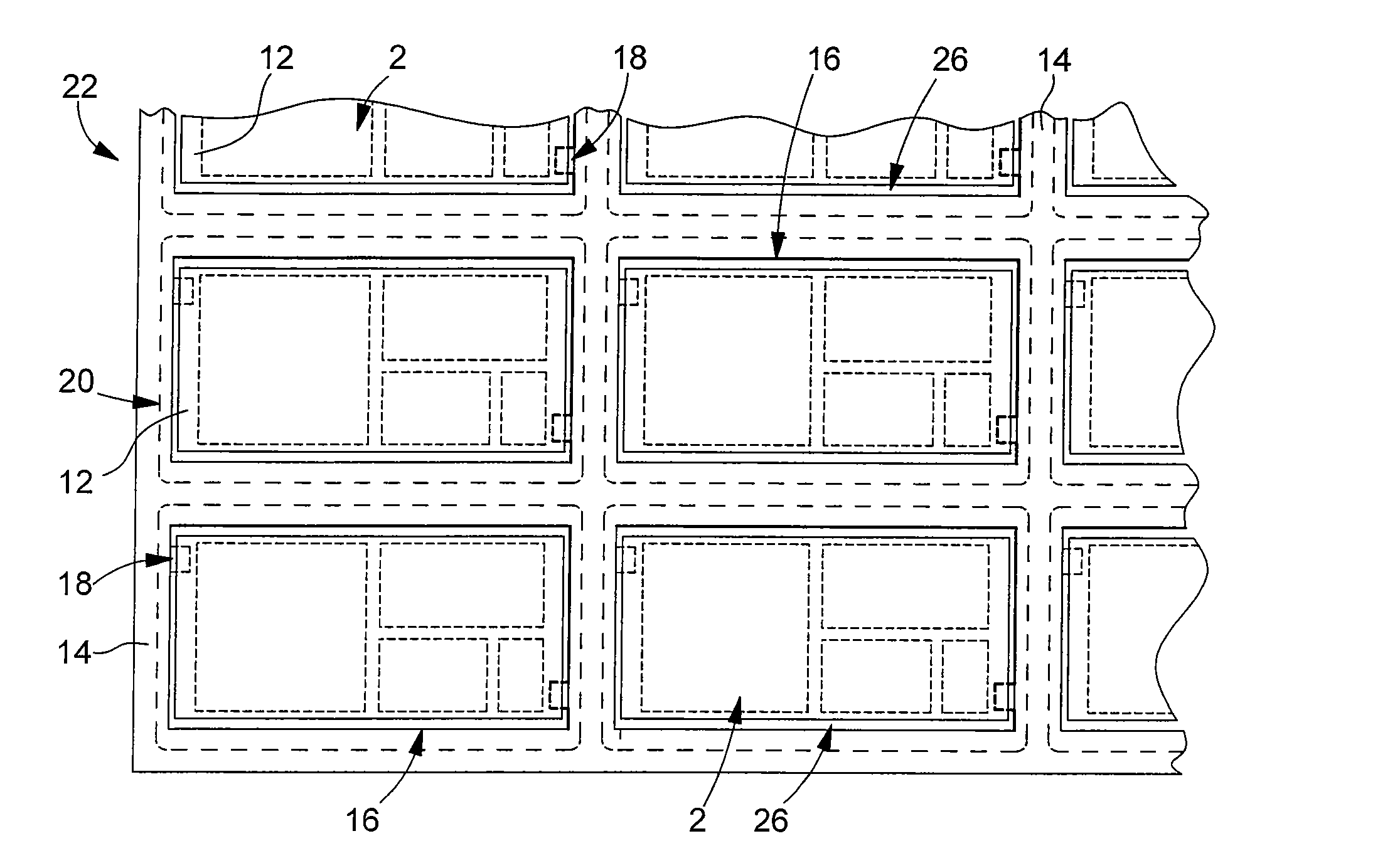
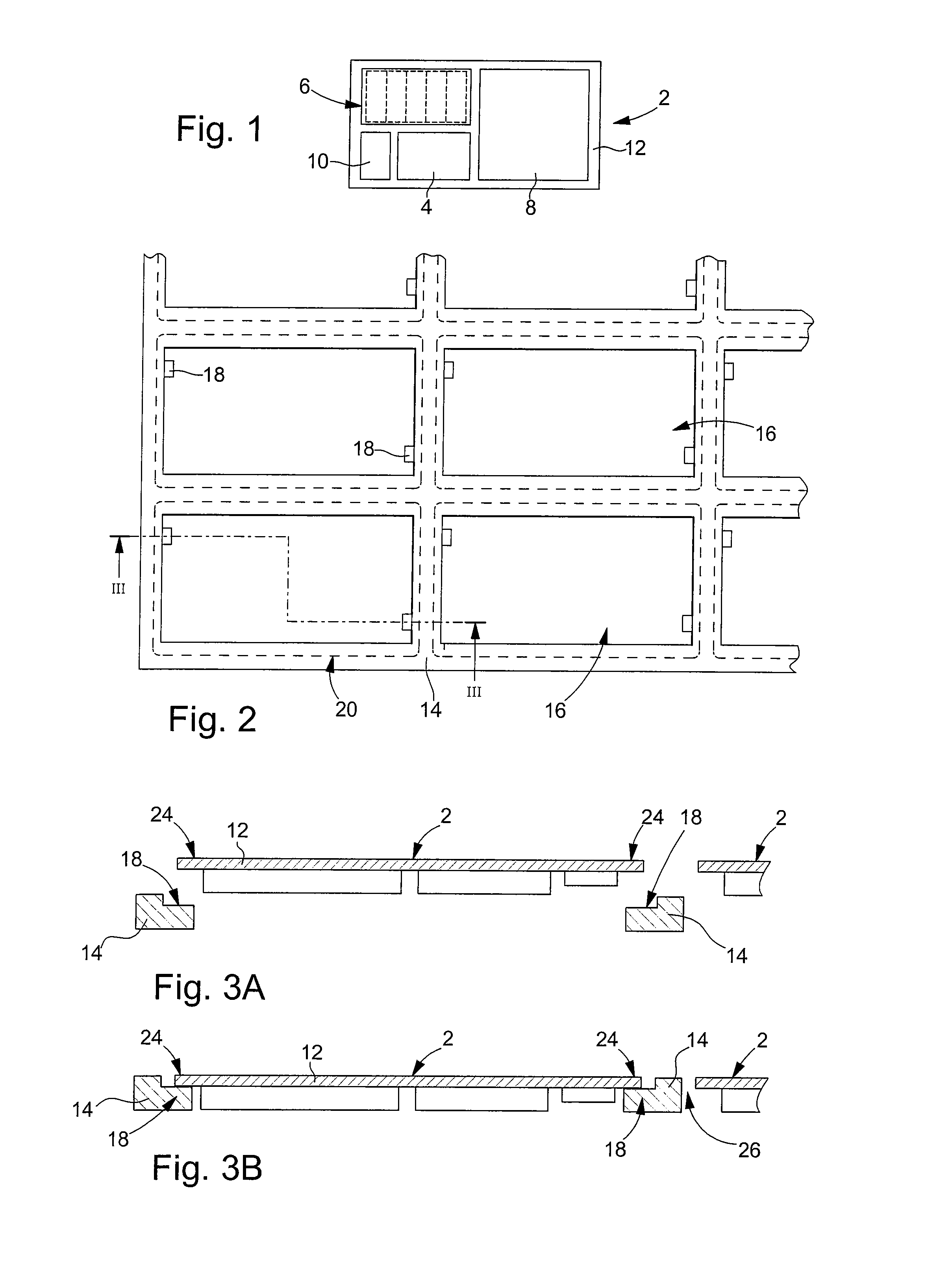
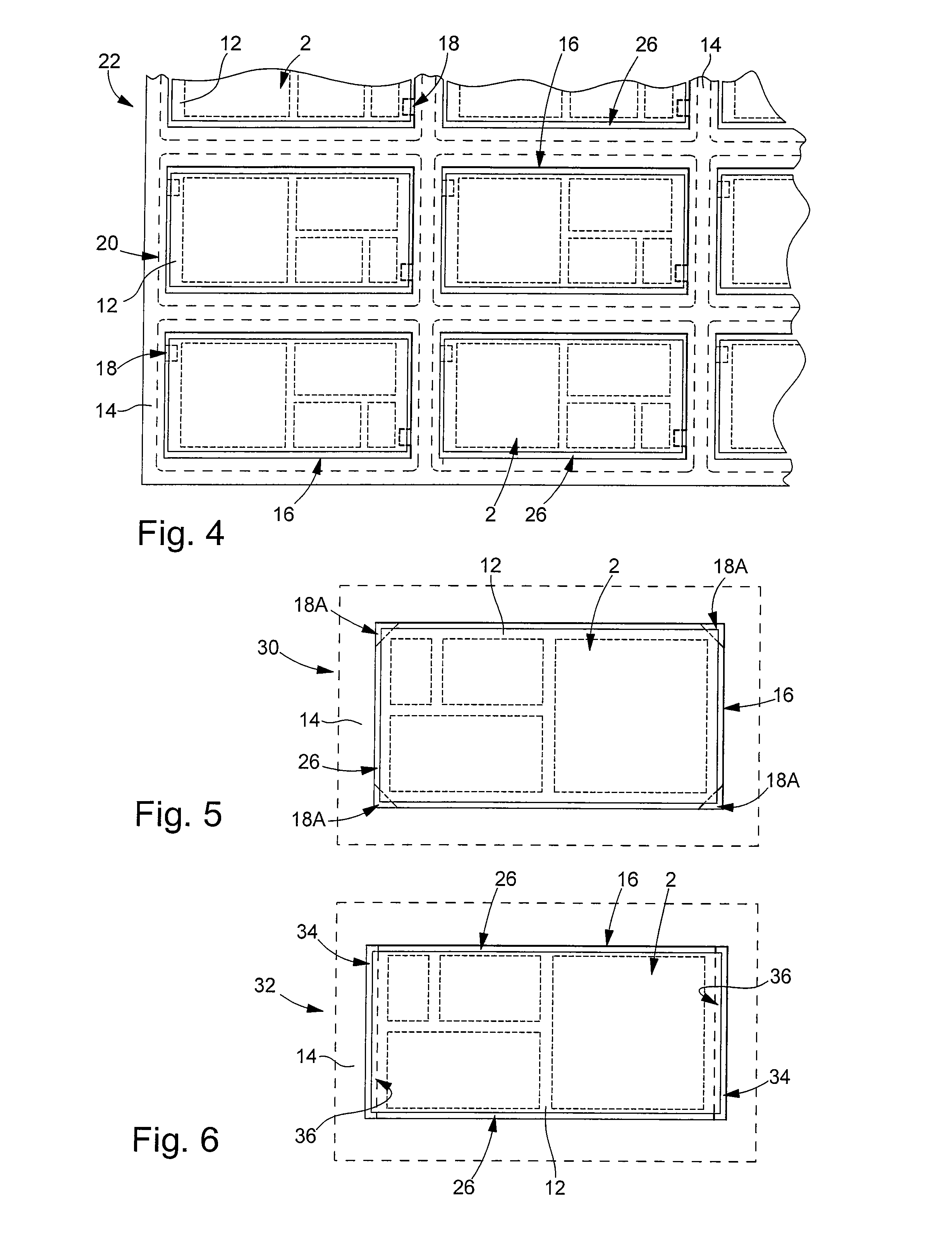
[0046]With reference to FIGS. 2 to 4, we will now describe an assembly according to the invention, which is produced in a card manufacturing method, also in accordance with the invention. The method of the invention is particularly well suited to manufacturing cards in batches, i.e. manufacturing several cards simultaneously. The assembly 22 shown partially in FIG. 4 includes several electronic modules 2 for manufacturing several batches of cards. However, it will be noted that the present invention is not limited to the batch manufacture of cards, but can also, in a particular variant, apply to card-by-card manufacture, i.e. individual card manufacture.

[0047]Assembly 22 includes a plate 14 that has at least one, at least partially through aperture 16, and at least one electronic module 2 at least partially housed in said at least one aperture 16. In the example shown in FIG. 2, plate 14 has a plurality of through apertures 16 and defines as many frames for electronic modules 2 as t...

second embodiment

[0063]FIG. 9 shows an assembly 50 according to the invention. The references that were described above will not be described again in detail here. This embodiment is characterized in that electronic module 2 is assembled to plate 14 via portions of adhesive strip 52, in particular two portions. In this embodiment, electronic module 2 is entirely contained within the corresponding aperture 16 and has no parts superposed on plate 14. The adhesive strip portions 52 define material connections between each electronic module and the pierced plate. These portions 52 can be arranged on either side of electronic module 2. In the example of FIG. 9, these portions 52 form a bridge between substrate 12 of module 2 and the peripheral area of aperture 16. These portions are arranged on the opposite side to the electronic elements carried by substrate 12. This example is in no way restrictive.

[0064]This second embodiment is characterized generally by the arrangement of strips formed of distinct m...

third embodiment

[0066]FIG. 11 shows an assembly according to the invention. This assembly 62 also includes a pierced plate 14 and electronic modules 2 arranged in apertures 16. These modules 2 are assembled to plate 14 here by heat-reactivatable adhesive wires 64. These heat-reactivatable adhesive wires 64 pass through plate 14 and, in particular, apertures 16. Each heat-reactivatable adhesive wire 64 is arranged to adhere to plate 14 and to the modules 2 through which it passes. In the example shown in FIG. 11, each electronic module 2 is held in the corresponding aperture 16 by two wires 64 arranged in proximity to two opposite edges of the module. The heat-reactivatable adhesive wire 64 can be a wire made of synthetic or natural material, or covered with adhesive. In another variant, the wire itself is formed by a solid resin, which can be made to adhere by applying heat or ultra-violet light. Of course, in another variant, an adhesive strip that passes through apertures 16 can form wire 64. In ...


PUM

PropertyMeasurementUnit
thicknessaaaaaaaaaa
areaaaaaaaaaaa
adhesiveaaaaaaaaaa

Abstract

The assembly (22) involved in the fabrication of electronic cards comprises a plate (14) exhibiting a plurality of apertures (16) in which are respectively housed a plurality of electronic modules (2). These electronic modules are assembled to the plate 14 by fixing means, in particular by fixing bridges leaving a slot (26) over the major part of the surround of the electronic module. For example the fixing means are formed by projecting parts (18) at the periphery of the apertures (16), these projecting parts exhibiting a smaller thickness than the thickness of the plate (14) and serving as supports for the electronic modules, in particular for a substrate (12) of these modules. Fixing is performed for example by welding or adhesive bonding. The invention also relates to an intermediate product formed by such an assembly and a filing material that fills at least the major part of the remaining space in the apertures (16). The invention also relates to a method of fabricating cards in which the assembly according to the invention is finally coated in a resin to form substantially plane cards.

Description

[0001]This is a National Phase Application in the United States of International Patent Application No. PCT / EP2007 / 055530 filed Jun. 5, 2007, which claims priority on European Patent Application No. 06012550.7, filed Jun. 19, 2006 and International Patent Application PCT / EP2006 / 008552, filed Oct. 5, 2006. The entire disclosures of the above patent applications are hereby incorporated by reference.FIELD OF THE INVENTION[0002]The present invention concerns a method of manufacturing cards that each include an electronic module, in particular, an electronic module comprising an electronic display. The card obtained from the method according to the invention is, for example, a bankcard, in particular, which conforms to the ISO standard. However, the present invention can also apply to electronic cards whose general profile is not rectangular, particularly circular cards. The present invention also concerns assemblies and intermediate products obtained within the scope of the method accor...

Claims


Application Information

Patent Timeline
Patent Type & Authority Applications(United States)
IPC IPC(8): G06K19/00B05D5/00B32B37/02
CPCG06K19/07745H01L2924/0002H01L2924/00
Inventor DROZ, FRANÇOIS
Owner NAGRAVISION SA
Why Eureka
Try Eureka