Tire Built in RFID Tag

a tire and rfid technology, applied in vehicle components, instruments, computing, etc., can solve the problems of reducing the quality of the tag, increasing the cost of the rfid tag itself, and the inability to mount three-dimensional rfid tags to some articles, so as to reduce the capacitive reactance of the circuit unit

Active Publication Date: 2010-04-15
ASIANA IDT
View PDF4 Cites 14 Cited by
  • Summary
  • Abstract
  • Description
  • Claims
  • Application Information

AI Technical Summary

Benefits of technology

[0024]In the present invention, a pair of tag radiators, which constitute the antenna of an RFID tire tag, are three-dimensionally implemented, so that the area facing a transponder and wings is increased, and thus the RFID tire tag identification rate of the transponder can be increased. Furthermore, in the present invention, the tag radiators are three-dimensionally arranged, are implemented to have a triangular wave or a circular wave shape, and are inserted into a tire in a vulcanization process of melting and processing tires, during a tire forming process, or after the tire forming process, so that the tire and the RFID tire tag can be securely coupled to each other when the tire is finally produced.
[0025]Furthermore, each of the radiators of the tire tag is divided into two region, that is, a first region and a second region (refer to the detailed description) depending on the location relative to the circuit unit, and the respective regions have different corrugation densities, so that impedance matching between the transponder and the antenna can be easily realized. In an embodiment of the present invention, the repetition period of the corrugation density of the second regions is set to be greater than that of the corrugation density of the first regions, so that the tag radiators of the second regions coarsely reduce the capacitive reactance of the circuit unit, and the tag radiators of the first regions finely reduce the capacitive reactance of the circuit unit.

Problems solved by technology

However, there are problems in that the three-dimensional RFID tag cannot be mounted to some articles, and in that the cost of the RFID tag itself is increased.
In this case, the quality of the tags may be lowered due to damage under the severe manufacturing conditions of a vulcanization process, which is a process that is performed after the tire forming process, that is, at a temperature between 200° C.˜250° C. and at a pressure of more than 30 Bar, and thus the tags may not perform their functions.
In addition, due to the rotational motion of a tire, a tag which is mounted in the tire may be damaged.

Method used


Image

  • Tire Built in RFID Tag
  • Tire Built in RFID Tag
  • Tire Built in RFID Tag

Examples


Embodiment Construction

[0049]The present invention is described in detail with reference to the accompanying drawings below.

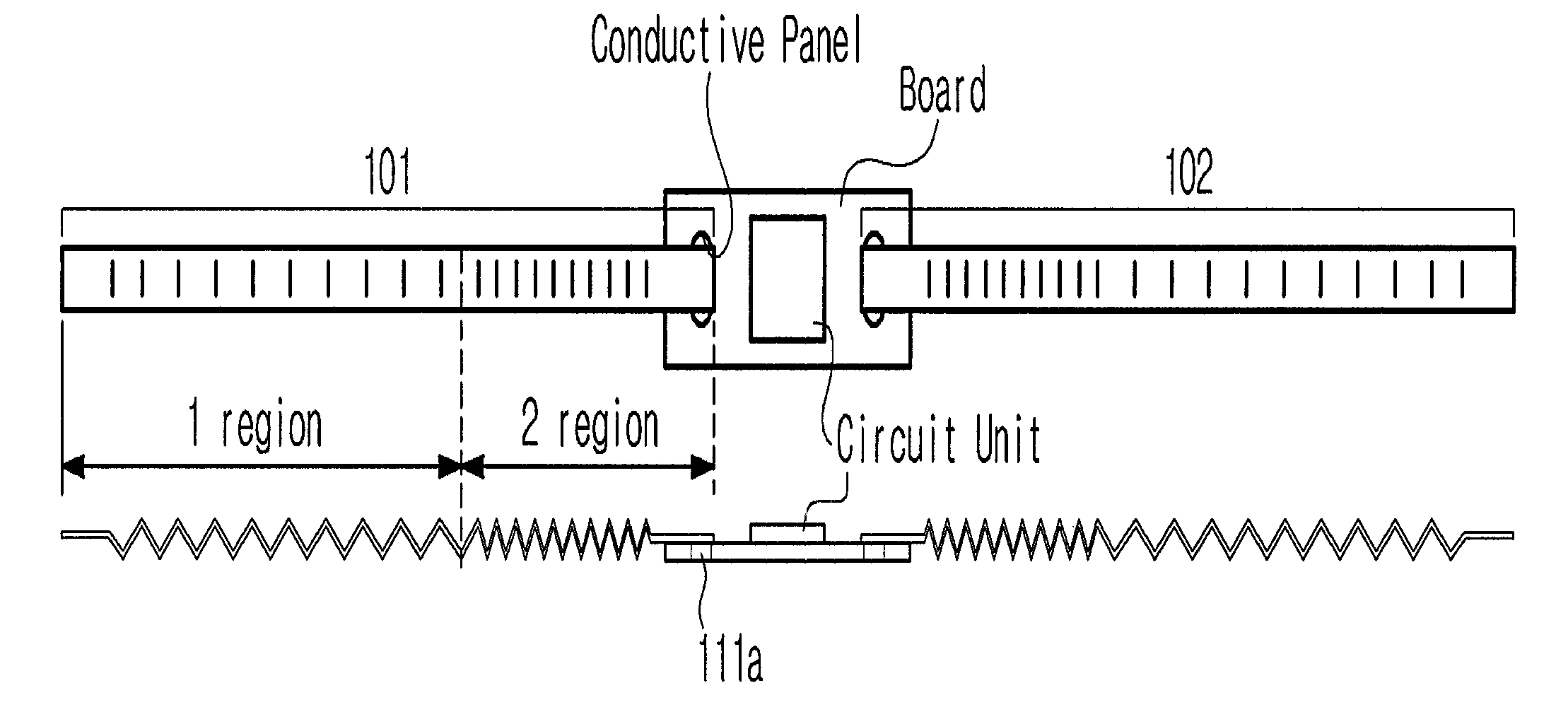
[0050]FIG. 1 shows an RFID tire tag according to an embodiment of the present invention.

[0051]The RFID tire tag, shown in the drawing, includes a circuit unit, and a pair of tag radiators 101 and 102, which are configured to resonate with radio waves that are transmitted from an external transponder (not shown). The circuit unit includes a circuit chip (not shown) for storing information about physical properties, such as the pneumatic pressure and temperature of a tire, and is coupled to a conductive panel through soldering.

[0052]When the external transponder (not shown) requests the information about the physical properties of a tire from the RFID tag, the circuit unit uses radio waves, which are provided by the external transponder, as a power source, and transmits the information, which is stored in the circuit unit, to the transponder through the tag radiators 101 and 102. Accor...


PUM


Abstract

Disclosed herein is a built-in RFID tire tag. The built-in RFID tire tag includes an antenna and a circuit unit. The antenna is mounted in a tire, and is configured to be operated by resonating with radio waves, which are transmitted from an RFID reader and to have a repetitive corrugated shape. The circuit unit is configured to be operated by being supplied with power using the radio waves. The antenna includes a pair of tag radiators. Each of the tag radiators is divided into a first region and a second region. The corrugation density of the second regions, which are close to the circuit unit, is greater than that of the first regions, which are not close to the circuit unit. The first regions, which depend on rotational motion of the tire, adapt flexibly to bending and torsion of the tire by the difference between the corrugation densities.

Description

TECHNICAL FIELD[0001]The present invention relates to a built-in RFID tire tag and, more particularly, to a built-in RFID tire tag, which is mounted in a tire during a tire manufacturing process, or after the tire manufacturing process, thus not only realizing secure fastening to the tire but also improving the identification rate of an RFID reader.BACKGROUND ART[0002]Generally, a Radio Frequency Identification (RFID) system is a non-contact identification system that enables a small-sized chip to be attached to various articles and transmits and processes information about the articles using radio frequencies, and includes a tag, which is provided with a chip and an antenna, and a reader, which reads information about articles stored in the chip.[0003]Generally, such an RFID tag is attached to the surface of a commodity or is inserted into an article. The success rate of detection (identification rate) varies according to the angle formed between the RFID tag and an RFID reader, wh...

Claims


Application Information

Patent Timeline
Patent Type & Authority Applications(United States)
IPC IPC(8): G06K19/077
CPCG06K19/07764G06K19/07749G06K19/077G06K19/07
Inventor JUNG, HONG CHAEMOON, SANG KUGYUN, JONG SUPYOON, JONG HWANKO, HO JEONGSEO, JEONG GEOLLIM, DONG UKKIM, NAM HOONKIM, SUNG CHUL
Owner ASIANA IDT
Why Eureka
Try Eureka