Eureka AIR delivers breakthrough ideas for toughest innovation challenges, trusted by R&D personnel around the world.

Coil spring

a coil spring and coil spring technology, applied in the field of coil springs, can solve the problems of preventing achieve the effects of improving the uneven distribution of stress, reducing oblateness, and shortening the close contact length

Active Publication Date: 2010-04-15
NHK SPRING CO LTD
View PDF11 Cites 6 Cited by
  • Summary
  • Abstract
  • Description
  • Claims
  • Application Information

AI Technical Summary

Benefits of technology

[0014]An object of the present invention is to provide a coil spring capable of achieving continuity of stress dispersion in a circumferential direction in a cross section to improve evenness of stress distribution while receiving load stably in a close contact state and reducing the oblateness to shorten a close contact length.
[0016]According to an aspect of the present invention, continuity of stress dispersion in a circumferential direction in a cross section can be achieved to improve evenness of stress distribution while receiving load stably in a close contact state and reducing the oblateness to shorten a close contact length.

Problems solved by technology

That is, a conventional coil spring including flat faces provided on a spring wire with a circular section or a rectangular section has a problem that evenness of stress distribution is prevented according to intermittence of stress dispersion in a circumferential direction in a cross section.

Method used


Image

  • Coil spring
  • Coil spring
  • Coil spring

Examples


embodiment 1

Effect of Embodiment 1

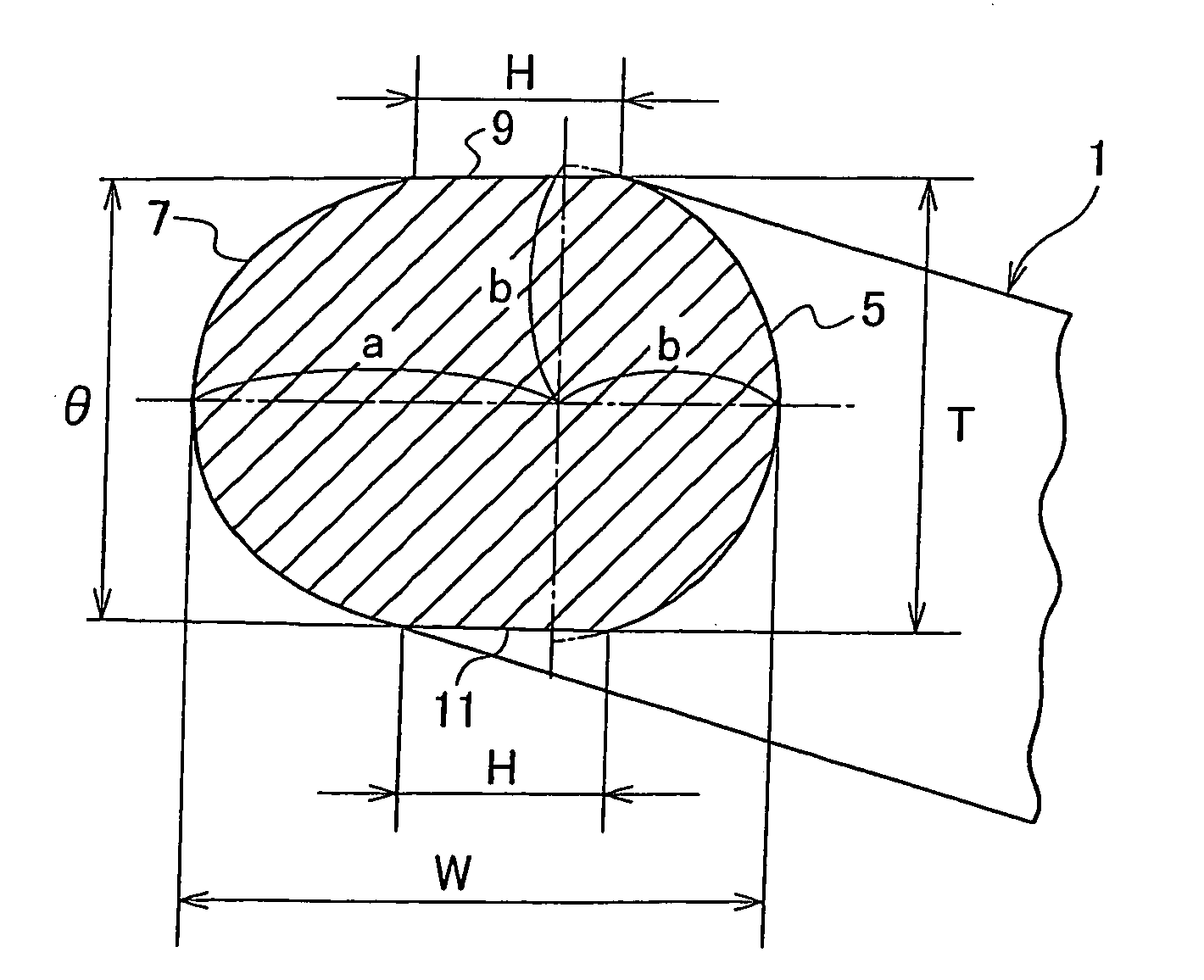
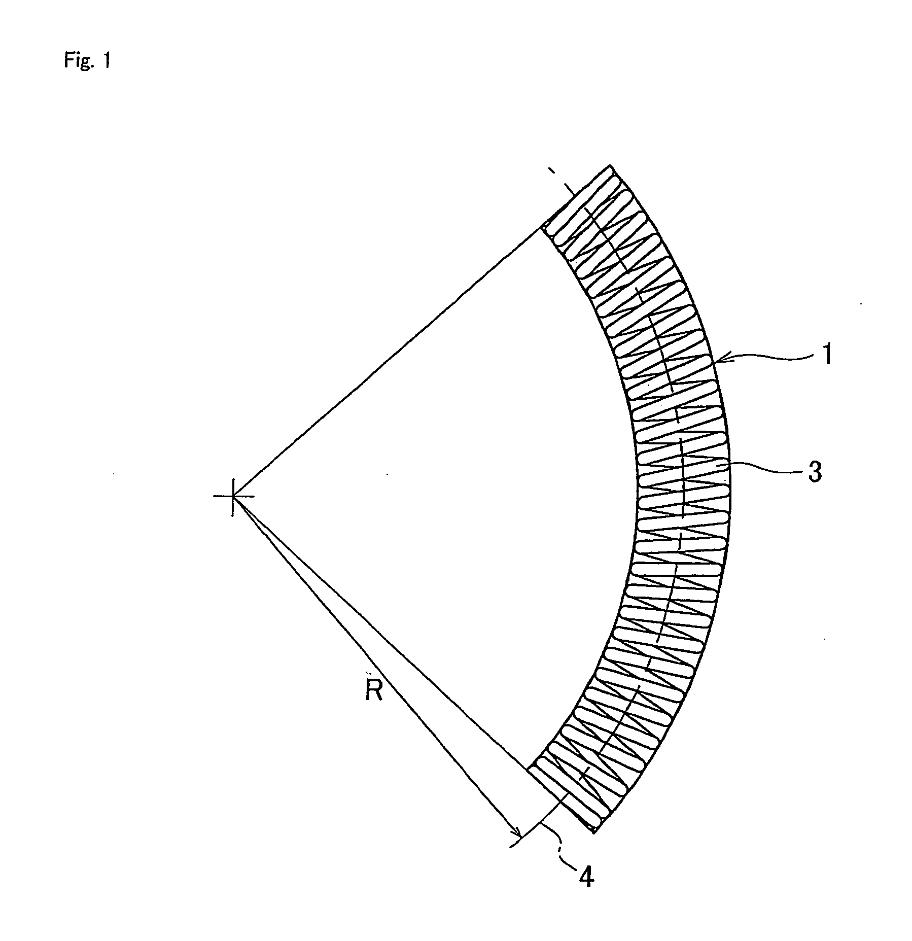
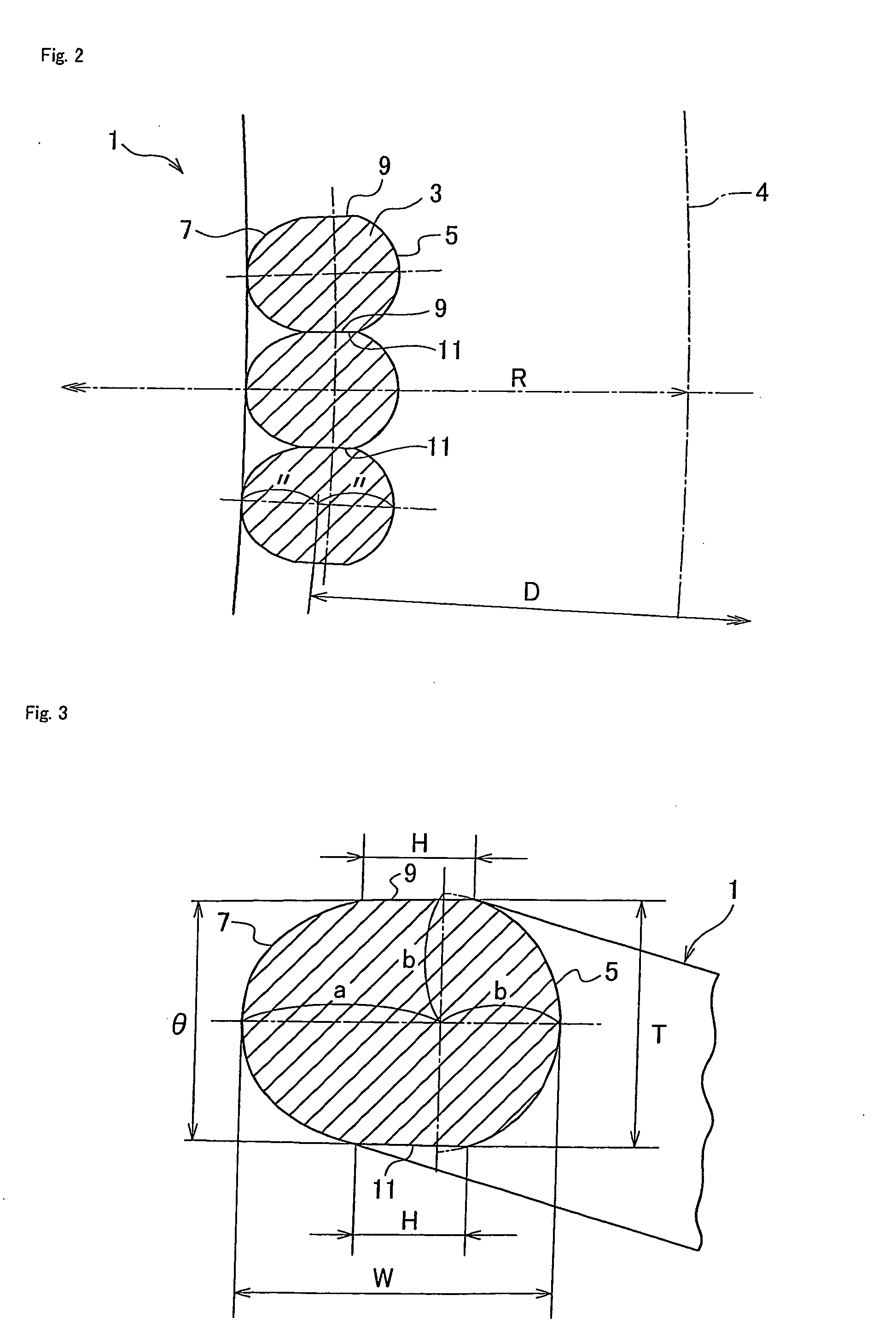
[0051]According to the embodiment of the present invention, the coil spring 1 comprises the spring wire 3 wound in a coil shape having the inner diameter side portion 5 and outer diameter side portion 7 in the cross section. One of the outer diameter side portion 7 or inner diameter side portion 5 is formed in the semi-circular shape expressed by x2+y2=b2, and the other thereof is formed in the non-circular shape with a long diameter “a” and a short diameter “b” expressed by (x / a)α+(y / b)α=1. The value of the “α” is set in a range of 1.85 to 2.45. The coil spring 1 further includes flat faces 9 and 11 provided between the inner diameter side portion 5 and the outer diameter side portion 7 on the peripheral shape of the spring wire in the cross section such that each flat face of each coil comes into contact with a flat face 9 or 11 of an adjacent coil in the axial direction along the axis line 4 of the coil spring 1. Therefore, continuity of stress dispersion in...


PUM


Abstract

A coil spring has a spring wire wound in a coil shape having an outer diameter side portion and an inner diameter side portion on a peripheral shape in a cross section thereof, one of the outer diameter side portion and inner diameter side portion formed in a semi-circular shape expressed by x2+y2=b2, the other thereof formed in a non-circular shape with a long diameter “a” and a short diameter “b” expressed by (x / a)α+(y / b)α=1, and value of the “α” set in a range of 1.85 to 2.45, and contact faces provided between the inner diameter side portion and the outer diameter side portion on the peripheral shape in the cross section such that each contact face comes into contact with a contact face of an adjacent coil in an axial direction along an axis line of the coil spring.

Description

BACKGROUND OF THE INVENTION[0001]The present invention relates to a coil spring that is used in a torsion spring for a torsional vibration absorbing device or the like.[0002]A conventional coil spring such as a torsion spring applied to, for example, a clutch disk is made of a spring wire with a circular section wound in a coil shape. The spring wire is provided with flat faces on a peripheral shape in a cross section thereof as contact faces.[0003]When load is applied to the coil spring until a coil shape is put in a close contact state or in a locked state, each flat face of each coil of the coil spring comes into contact with a flat face of an adjacent coil to receive the load stably and suppress displacement in a diameteral direction of the coil.[0004]In the coil spring, however, stress acting on an inner side portion in the diametral direction of the coil (an inner diameter side portion) is generally higher than stress acting on an outer side portion in the diametral direction ...

Claims


Application Information

Patent Timeline
IPC IPC(8): F16F1/06
CPCF16H45/02F16F1/042F16F1/00F16F1/04
Inventor FENIOUX, DANIELKATO, NOBUHARUYABUSHITA, TAKESHI
Owner NHK SPRING CO LTD
Why Eureka
Eureka Blog
Learn More