System and method for providing gyroscopic stabilization to a wheeled vehicle

a technology for stabilizing systems and wheels, applied in the direction of other supporting devices, vehicle components, cycle equipment, etc., can solve the problems of excessive steering ability of riders, achieve greater stability, prevent jackknife movement, and limit the ability of riders to execu

Inactive Publication Date: 2010-04-15
THE GYROBIKE
View PDF34 Cites 45 Cited by
  • Summary
  • Abstract
  • Description
  • Claims
  • Application Information

AI Technical Summary

Benefits of technology

[0007]This invention overcomes the disadvantages of the prior art by providing a stabilizing system and method for wheeled vehicles (for example, motorized and human-powered bicycles, unicycles and / or tricycles, as well as specialized devices, such as hand-pedaled and reclining cycles) that affords the rider no restriction on the full range of movements (banks, leans, etc.) common to cycles, but that provides greater stability during turns and other maneuvers so that an unintentional bank or tilt (potentially leading to a fall) is less likely, even at relatively slow speeds and startup. A rotating mass of predetermined mass-value and radial mass-distribution is provided (in an illustrative embodiment) coaxially with the front axle. The mass is supported on bearings so as to freewheel with respect to the rotation of the front wheel. As such it can be induced to spin significantly faster than the front wheel thereby generating a gyroscopic effect at the front wheel about the axle. The rotating mass can define a flywheel structure in an illustrative embodiment. This gyroscopic effect induced on the wheel influences the steering of the wheel by the rider. Due to precession, the wheel tends to follow any excessive bank by the bicycle, ensuring that the rider can “steer-out-of” an unintentional tilt. Likewise, the gyroscopic effect limits the rider's ability to execute excessive steering, thereby preventing jackknife movements. The mass can be an electric-motor-driven flywheel within a shell housing that includes a battery, control system and drive motor. The drive motor includes a frictional drive tire that engages the surface of the flywheel under a movable spring pressure that accommodates any unevenness between the motor and the surface of the flywheel, so as to avoid possible damage to the motor.

Problems solved by technology

Likewise, the gyroscopic effect limits the rider's ability to execute excessive steering, thereby preventing jackknife movements.

Method used


Image

  • System and method for providing gyroscopic stabilization to a wheeled vehicle
  • System and method for providing gyroscopic stabilization to a wheeled vehicle
  • System and method for providing gyroscopic stabilization to a wheeled vehicle

Examples


Embodiment Construction

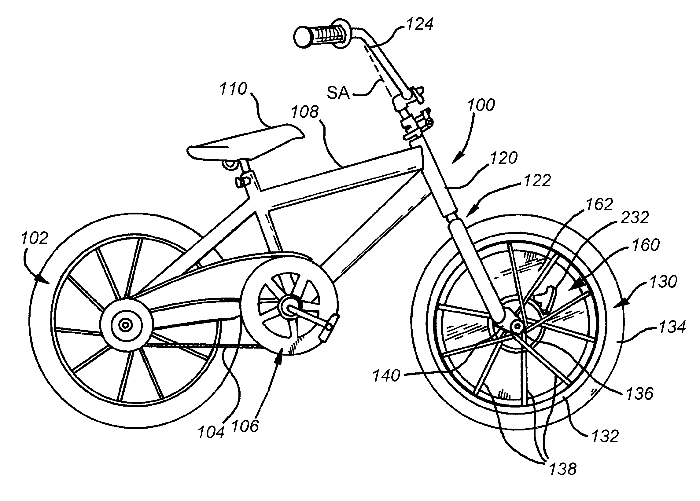
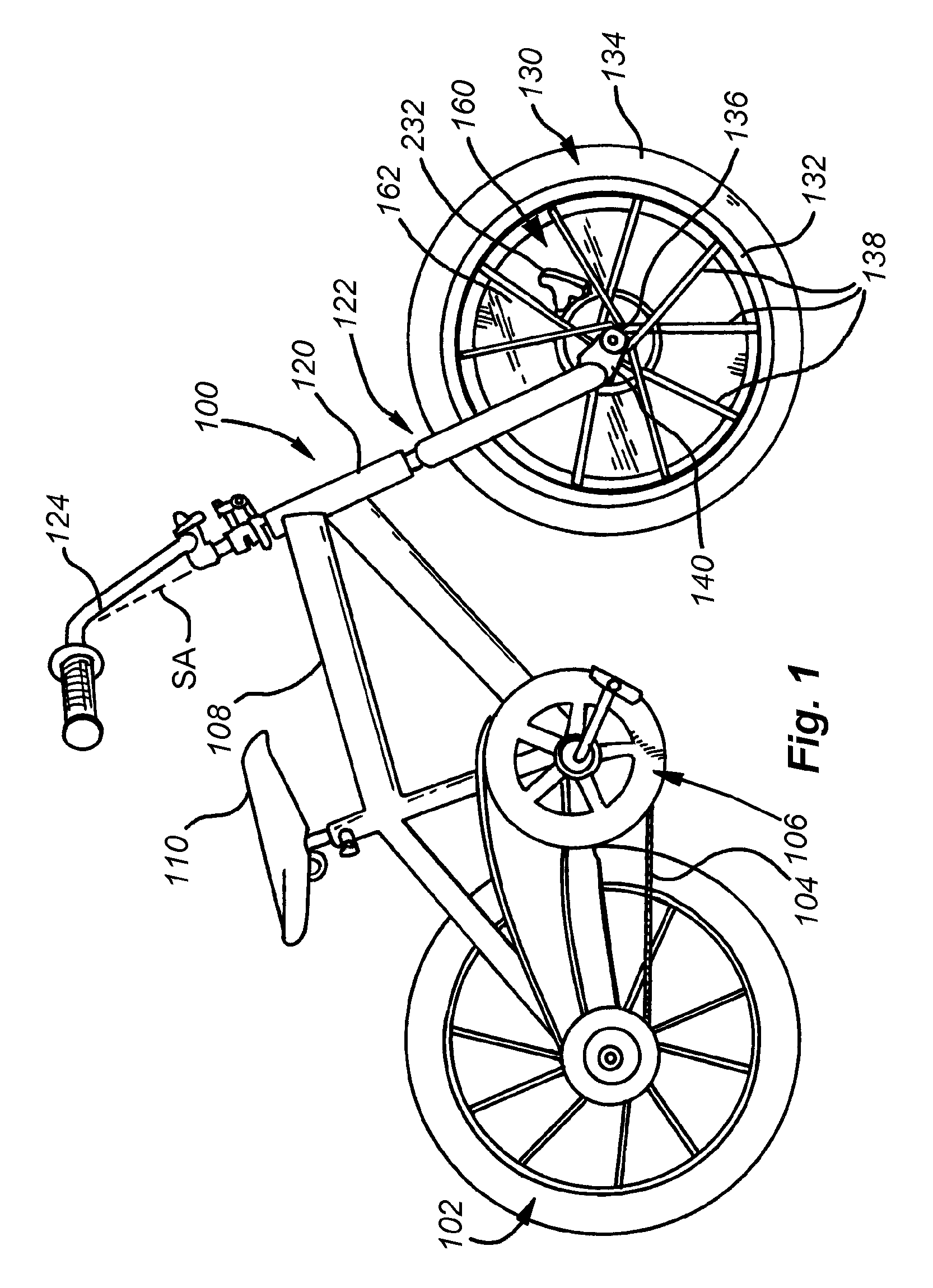
[0037]A bicycle 100 having a stabilizing system according to an illustrative embodiment of this invention is shown in FIG. 1. This bicycle is exemplary of a certain size and style of human-powered two-wheeled vehicle that is particularly adapted for smaller children. The terms“bicycle” and “vehicle” as used herein are expressly intended to refer to any type of two-wheeled vehicle (including certain powered vehicles) that would benefit from the front-wheel gyroscopic stabilizing effect to be described herein.

[0038]The bicycle 100 includes a conventionally mounted rear wheel assembly 102, driven by a chain 104 that is, in turn operatively connected to a pedal crank assembly 106. The bicycle frame 108 is constructed from a set of joined tubular members that support a seat 110 above the frame 108 and is general alignment with the pedal crank assembly 106 so that a rider (see below) can reach and operate the pedals with his or her feet.

[0039]The front of the frame 108 includes a down-tub...


PUM


Abstract

This invention provides a stabilizing system and method for two-wheeled vehicles that affords the rider no restriction on the full range of movements (banks, leans, etc.) common to bicycles, but that provides greater stability during turns and other maneuvers so that an unintentional bank or tilt (potentially causing a fall) is less likely, even at relatively slow speeds and startup. A rotating mass of predetermined mass-value and radial mass-distribution is provided coaxially with the front axle. The mass is supported on bearings so as to freewheel with respect to the rotation of the front wheel. As such it can be induced to spin significantly faster than the front wheel thereby generating a gyroscopic effect at the front wheel about the axle. This gyroscopic effect influences the steering of the wheel by the rider. Due to precession, the wheel tends to follow any excessive bank by the vehicle, ensuring that the rider can “steer-out-of” an unintended tilt or bank. Likewise, the gyroscopic effect limits the rider's ability to execute excessive steering, thereby preventing jackknife movements. The mass can be an electric-motor-driven flywheel within a shell housing that includes a battery, control system and drive motor. The drive motor engages a surface of the flywheel with a drive tire in a resilient manner to reduce potential damage to the motor.

Description

RELATED APPLICATIONS[0001]This application is a continuation-in-part of co-pending patent application. Ser. No. 11 / 967,491, filed Dec. 31, 2007, entitled SYSTEM AND METHOD FOR PROVIDING GYROSCOPIC STABILIZATION TO A TWO-WHEELED VEHICLE, the entire disclosure of which is herein incorporated by reference, which is a divisional of U.S. patent application Ser. No. 11 / 170,993, filed Jun. 30, 2005, entitled SYSTEM AND METHOD FOR PROVIDING GYROSCOPIC STABILIZATION TO A TWO-WHEELED VEHICLE, now U.S. Pat. No. 7,314,225, the entire disclosure of which is herein incorporated by reference.FIELD OF THE INVENTION[0002]This invention relates to stabilization systems for wheeled vehicles and training devices for new riders of such vehicles.BACKGROUND OF THE INVENTION[0003]Learning to ride a bicycle, or similar human-powered vehicle, is one of the more difficult physical challenges faced by young children (and some older ones). Children must develop awareness of what are, in essence, complex Newtoni...

Claims


Application Information

Patent Timeline
Patent Type & Authority Applications(United States)
IPC IPC(8): B62H7/00
CPCB62M1/10B62H7/00
Inventor REICHSTETTER, DANIELLARETAILLEAU, SASCHA M.MCCALL, CHARLES S.SIGWORTH, NATHANHUPPI, BRIAN Q.VON BEHRENS, PETER E.WHITMAN, SCOTTMURNEN, HANNAHSPERLING, DEBORAHNILES, AUGUSTA
Owner THE GYROBIKE
Why Eureka
Try Eureka