Road Milling Machine

a technology of road milling machine and rotary milling machine, which is applied in the direction of roads, transportation and packaging, roads, etc., can solve the problem that the ladder cannot be damaged, and achieve the effect of facilitating the climb to the driver's position

Active Publication Date: 2010-04-15
WIRTGEN GMBH
View PDF9 Cites 29 Cited by
  • Summary
  • Abstract
  • Description
  • Claims
  • Application Information

AI Technical Summary

Benefits of technology

[0028]A particular compact structure can be obtained by having the bottom portion of that stile of the top sub-section of the ladder against which the rung of the bottom sub-section rests in the folded-in position extend obliquely to the other stile of the top sub-section, thus causing the rung of the bottom sub-section not to project laterally when folded against the stile of the top sub-section.
[0029]In the folded-out position, the bottom sub-section of the ladder is securely held by a stop member which is supported against the top sub-section of the ladder. In the folded-in position, the bottom sub-section of the ladder can preferably be locked to the top sub-section by a fastening member. The fastening member may be a fastening member which locks the bottom sub-section in the folded-in position by a snap or latching action and which can easily be released to allow the bottom sub-section to be folded out.
[0030]To make the climb to the driver's position easier, the ladder preferably has a hand-hold member which projects upwards beyond the ladder in the vertical position and which the driver of the machine can use to hold himself secure when climbing the ladder. The hand-hold member may be of different forms. It may also act as a safeguard against falling-off sideways. As well as performing its safety function, the hand-hold member may also serve as a lever for pivoting the ladder from the vertical position to the horizontal position or vice versa.

Problems solved by technology

However, should the ladder not be in a state where it is folded upwards while the machine is being used to do work, the ladder cannot be damaged against obstacles which suddenly make an appearance in the working range.

Method used


Image

  • Road Milling Machine
  • Road Milling Machine
  • Road Milling Machine

Examples


Embodiment Construction

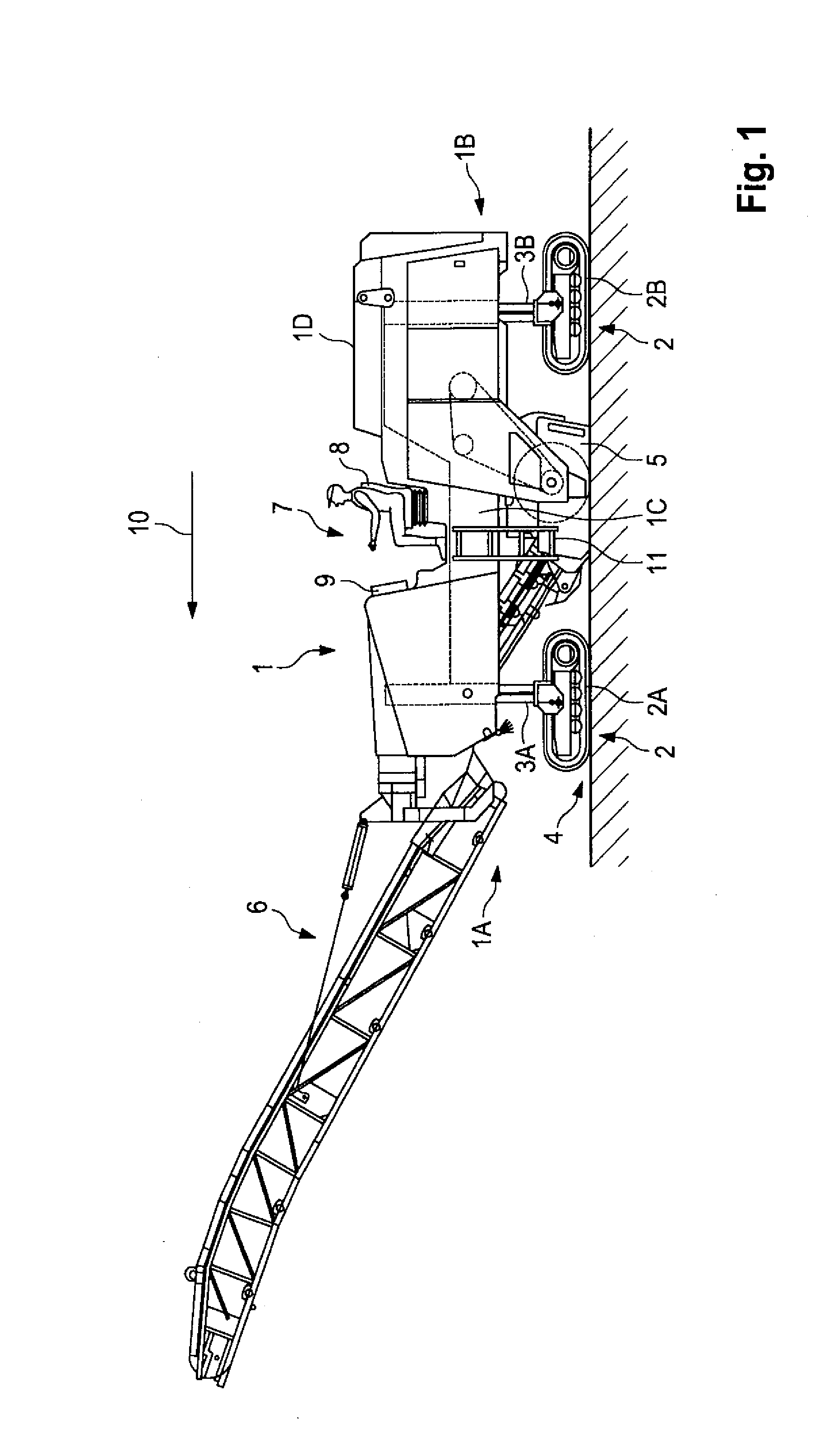
[0039]FIG. 1 shows the principal components of a road-milling machine which has a driver's position. The road-milling machine has a frame 1 and running gear 2. The running gear 2 of the milling machine comprises four track-laying units 2A, 2B which are arranged at the front and rear ends on the two sides of the frame 1 of the machine. The frame 1 of the machine and the running gear 2 are connected together by means of piston-and-cylinder arrangements 3A, 3B, thus allowing each track-laying unit to be adjusted in the heightwise direction. The track-laying units 2A, 2B may also be referred to simply as tracks. The road-milling machine may also use wheels instead of tracks. The tracks or wheels may generally be referred to as ground engaging supports.

[0040]The frame 1 of the milling machine carries a milling arrangement 5 which is arranged below the frame of the machine and a feeding arrangement 6 for the milled-away material which is arranged at the front end of the frame of the machi...


PUM


Abstract

The invention relates to a road-milling machine which has a ladder 11 to allow the driver's position 7 of the civil engineering machine to be climbed to easily. The ladder is mounted on one 1B of the two longitudinal sides of the frame 1 of the machine to be pivotable about an axis of pivot 27 extending substantially at right angles to the direction of travel. The ladder can thus be folded upwards to widen the working range of the machine. However, should the ladder not be in a state where it is folded upwards while the machine is being used to do work, the ladder cannot be damaged against obstacles which suddenly make an appearance in the working range. Should the ladder hit against an obstacle, the ladder is able to move out of the way of the obstacle by pivoting out of the vertical position in the opposite direction to the direction of travel. A further advantage of the ladder lies in the fact that the ladder can easily be folded upwards or downwards not only from the ground but also from the driver's position.

Description

[0001]This application claims benefit of German Patent Application DE 20 2008 013 393.9, filed Oct. 9, 2008.BACKGROUND OF THE INVENTION[0002]1. Field of the Invention[0003]The invention relates to a road-milling machine.[0004]2. Description of the Prior Art[0005]Civil engineering machines of different designs are known for underground and above-ground construction. What are used for the construction of roads are self-propelled road-building machines, which include for example known road-milling machines. Known road-milling machines have a driver's position for the driver of the machine.[0006]Because of the relatively large dimensions of road-milling machines, the driver's position is arranged at a relatively great height above the ground. For climbing to the driver's position, road-milling machines therefore have a ladder which is arranged on one side of the frame of the machine below the driver's position. To make the climb to the driver's position easier, the ladder should reach t...

Claims


Application Information

Patent Timeline
Patent Type & Authority Applications(United States)
IPC IPC(8): E06C5/04E06C5/06E01C23/088
CPCB60R3/02E06C5/04E01C23/088E01C2301/30
Inventor KRAMER, THOMASBERNING, CHRISTIANBUSLEY, PETER
Owner WIRTGEN GMBH
Why Eureka
Try Eureka