Electrical extension cord

a technology of extension cords and extension cords, which is applied in the direction of coupling device connections, electrical equipment, instruments, etc., can solve the problems of short length of electrical power cords on such tools and equipment, inability to provide uncluttered electrical power to a large work area, and elevated work areas

Inactive Publication Date: 2010-04-15
HAUSER BRUCE
View PDF32 Cites 49 Cited by
  • Summary
  • Abstract
  • Description
  • Claims
  • Application Information

AI Technical Summary

Benefits of technology

[0013]For purposes of summarizing the invention, certain aspects, advantages and novel features of the invention have been described herein. It is to be understood that not necessarily all such advantages may be achieved in accordance with any particular embodiment of the invention. Thus, the invention may be embodied or carried out in a manner that achieves or optimizes one advantage or group of advantages as taught herein without necessarily achieving other advantages as may be taught or suggested herein.

Problems solved by technology

A primary challenge of known devices such as those disclosed in U.S. Pat. No. 6,486,407 and U.S. Pat. No. 7,229,302, is the ability to provide electrical sources for electric heavy duty equipment and tools from a single source dispersed to several of said equipment and tools at the same time and spread out about a general and / or elevated location.
Such a clustering presents safety concerns due to the close proximity of manipulable electrical couplings and the increased trip hazards presented by the collection of close proximity electrical couplings.
The aforementioned devices consist of source electrical cords arranged to transmit electrical power to a housing that distributes to short proximate cords terminating with female electrical connectors and lacking the ability to provide uncluttered electrical power to a large work area, particularly an elevated work area.
Further, the electrical power cords on such tools and equipment do not come in standard lengths and are generally of short length.
Use of such tools and equipment can lead to a local cluttering effect within or adjacent to working areas and / or the need for additional extension cords to reach from the power cord strip to multiple specific working locations.

Method used


Image

  • Electrical extension cord
  • Electrical extension cord
  • Electrical extension cord

Examples


Embodiment Construction

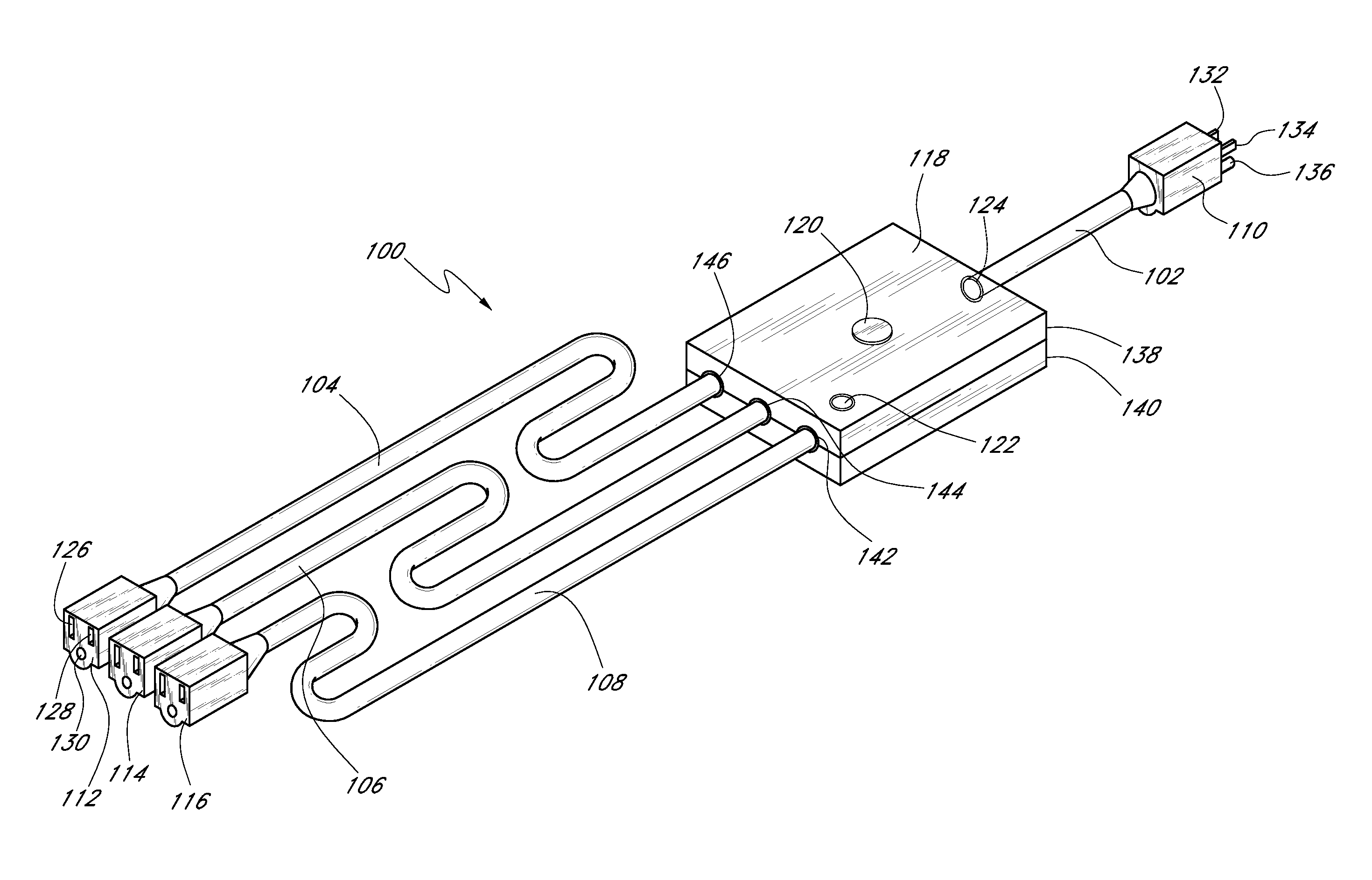
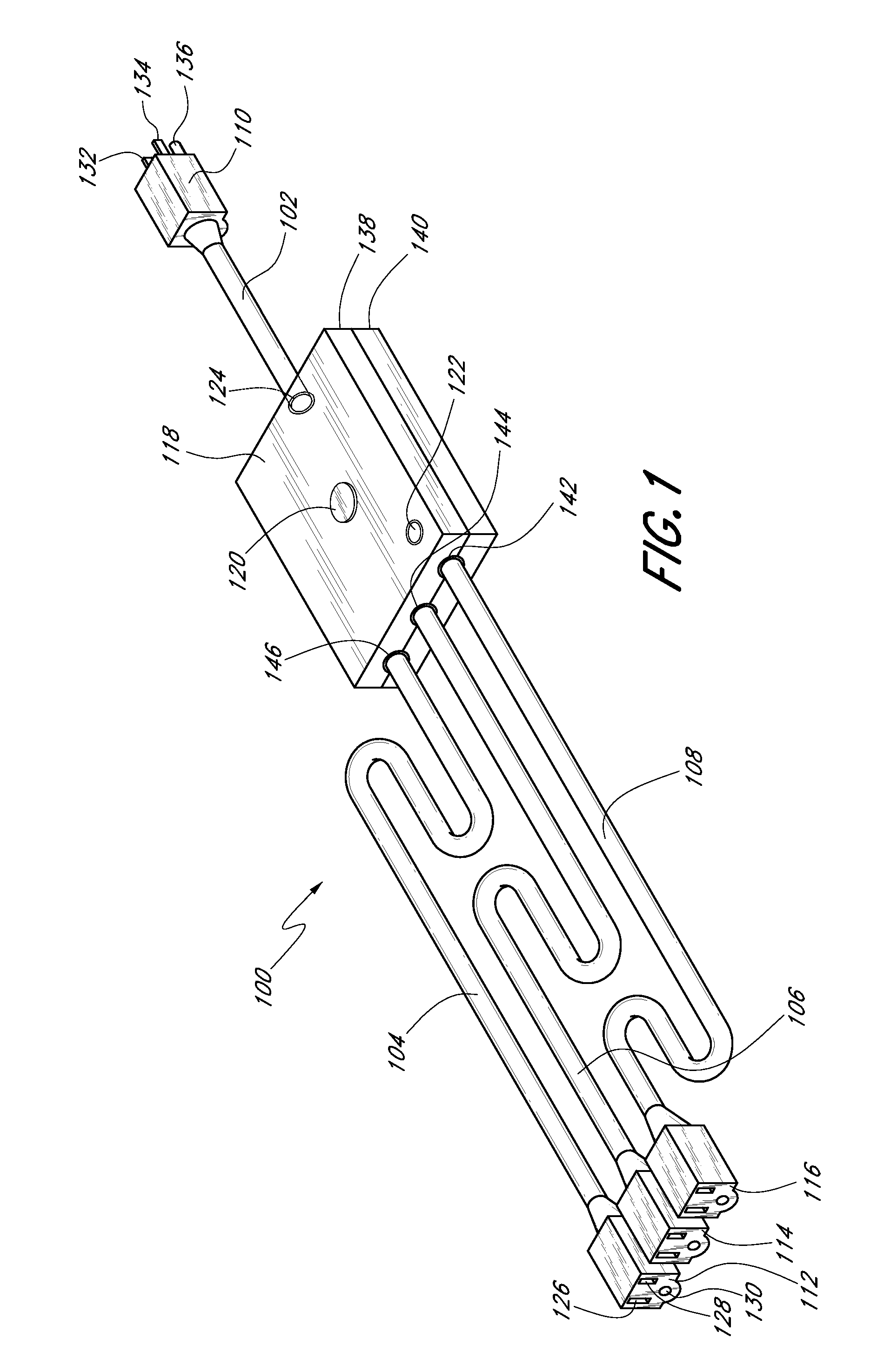
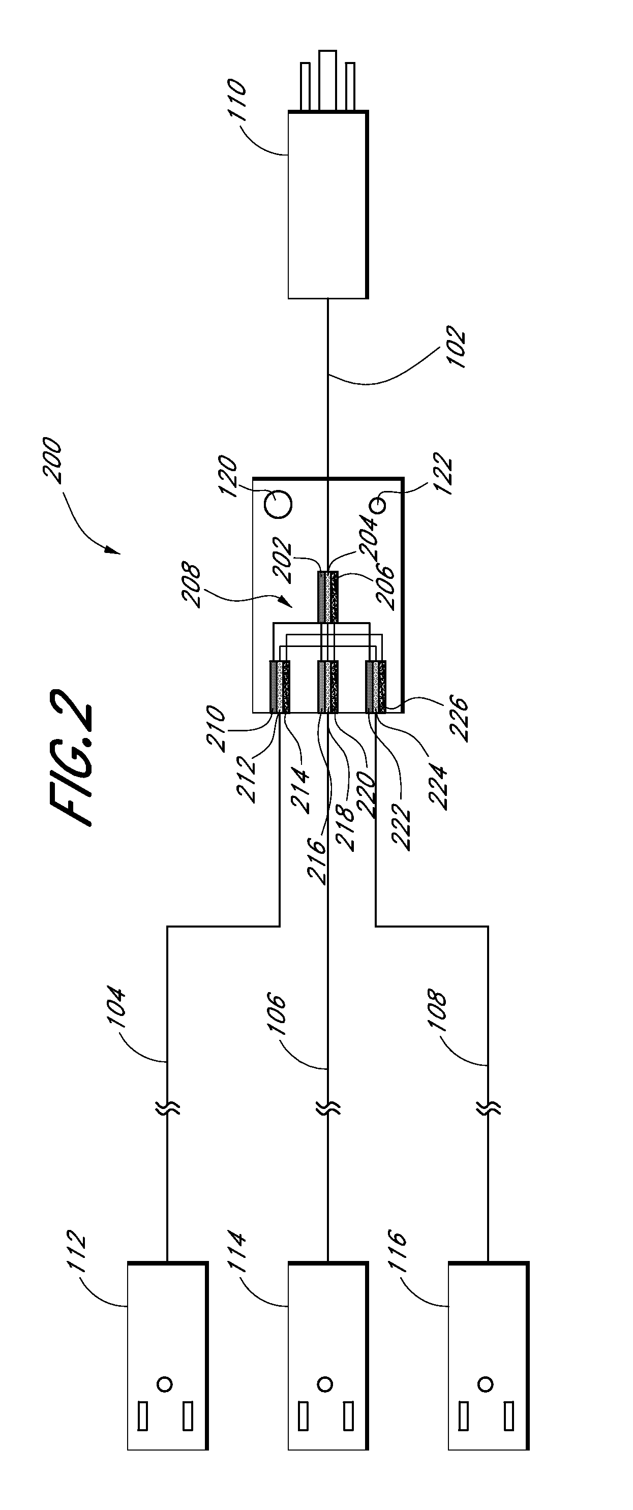
[0019]The associated drawings and specification discuss aspects and features of the present invention in the context of several different embodiments of electrical power extension cords that are configured for concurrent multi-appliance use about an extended working area. Discussing these features in connection with construction applications provides clarity and consistency in presenting these inventive features and concepts. However, it is to be understood that the features and concepts discussed herein can be applied to industries other than the construction industry. For example, extended length extension cords can be applied to other industrial applications such as manufacturing, wood-working, or the like.

[0020]In fact, the principles discussed herein can be used in any application that would benefit from an electrical extension cord having a broad radial range that reduces the number of external extension cords required about an extended working area involving industrial tools ...


PUM


Abstract

An electrical extension cord to conduct and provide electrical power to multiple locations on a job site includes a power supply portion having an electrical connector configured to be received in an electrical outlet that provides a source of electricity. The extension cord includes a power distribution portion having at least a first electrical cord and at least a second electrical cord with each cord having an electrical connector configured to receive a mating connector of an electrically powered device and the extension cord further includes a junction that electrically couples the power supply portion and the power distribution portion with the coupling being enclosed by a housing. The first cord and the second electrical cord define a length of at least six feet measured from the housing.

Description

CROSS-REFERENCE TO RELATED APPLICATIONS[0001]This application claims the benefit of U.S. Provisional Application No. 61 / 101,393, which was filed on Sep. 30, 2008. The entirety of the priority application is hereby incorporated by reference.BACKGROUND OF THE INVENTION[0002]1. Field of the Invention[0003]The present invention relates to electrical distribution devices and, more particularly, to an electrical extension cord device.[0004]2. Description of the Related Art[0005]Electrical extension cords, in particular electrical power cord strips having single input and multiple output, allow for increased utility of available electrical power sources. The typical commercial or residential building electrical outlet includes one or two electrical sources. An electrical power cord strip provides a plurality of typically female connectors for a plurality of devices to connect to for proper electrical power source. In particular, in industrial applications, where heavy duty equipment and to...

Claims


Application Information

Patent Timeline
Patent Type & Authority Applications(United States)
IPC IPC(8): G08B21/00H01R11/00
CPCH01R13/70H01R25/003H01R13/717
Inventor HAUSER, BRUCE
Owner HAUSER BRUCE
Why Eureka
Try Eureka