Objective lens, nosepiece and inverted microscope equipped therewith

a technology of inverted microscope and objective lens, which is applied in the field of objective lens, nosepiece and inverted microscope equipped therewith, can solve the problem of becoming impossible to obtain a clear image, and achieve the effect of reducing focus shi

Active Publication Date: 2010-04-15
NIKON CORP
View PDF4 Cites 10 Cited by
  • Summary
  • Abstract
  • Description
  • Claims
  • Application Information

AI Technical Summary

Benefits of technology

[0013]According to the present invention, it becomes possible to reduce focus shift caused by thermal expansion of a lens barrel of an objective lens.

Problems solved by technology

When the focus shifting exceeds the depth of focus of the objective lens, it becomes impossible to obtain a clear image.

Method used


Image

  • Objective lens, nosepiece and inverted microscope equipped therewith
  • Objective lens, nosepiece and inverted microscope equipped therewith
  • Objective lens, nosepiece and inverted microscope equipped therewith

Examples


Embodiment Construction

[0017]An embodiment according to the present invention is explained below with reference to accompanying drawings.

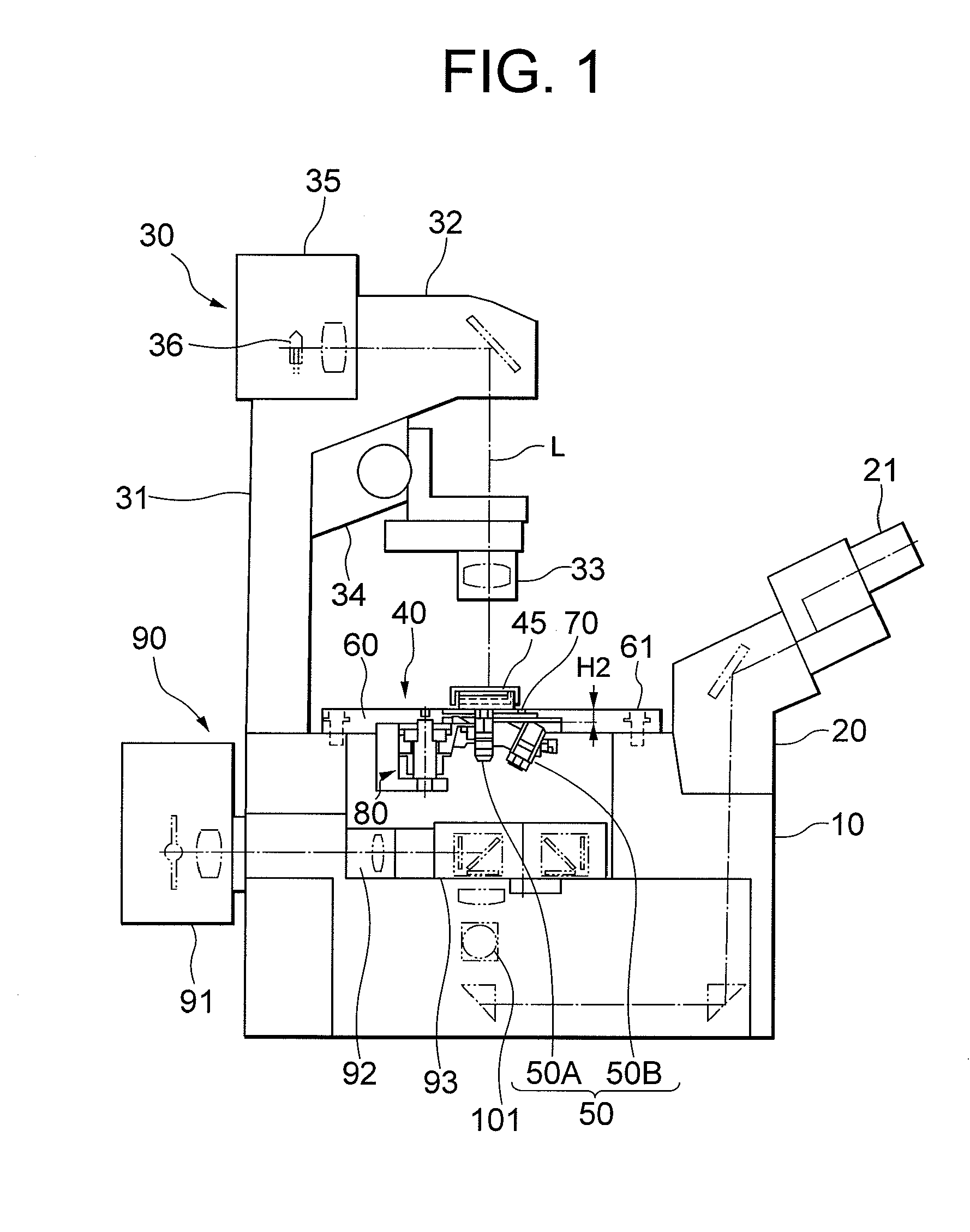
[0018]FIG. 1 is a schematic diagram of an inverted microscope seen from a side according to an embodiment of the present invention.

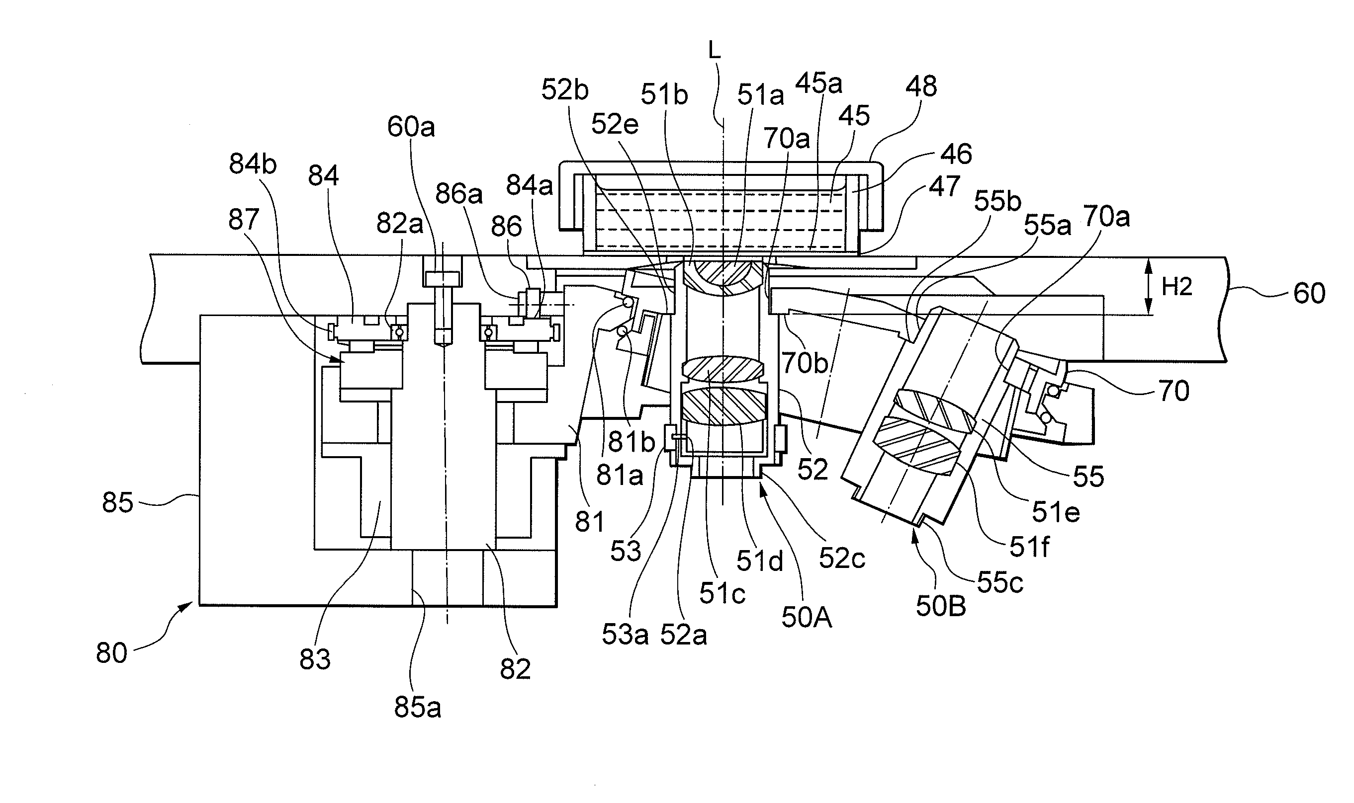
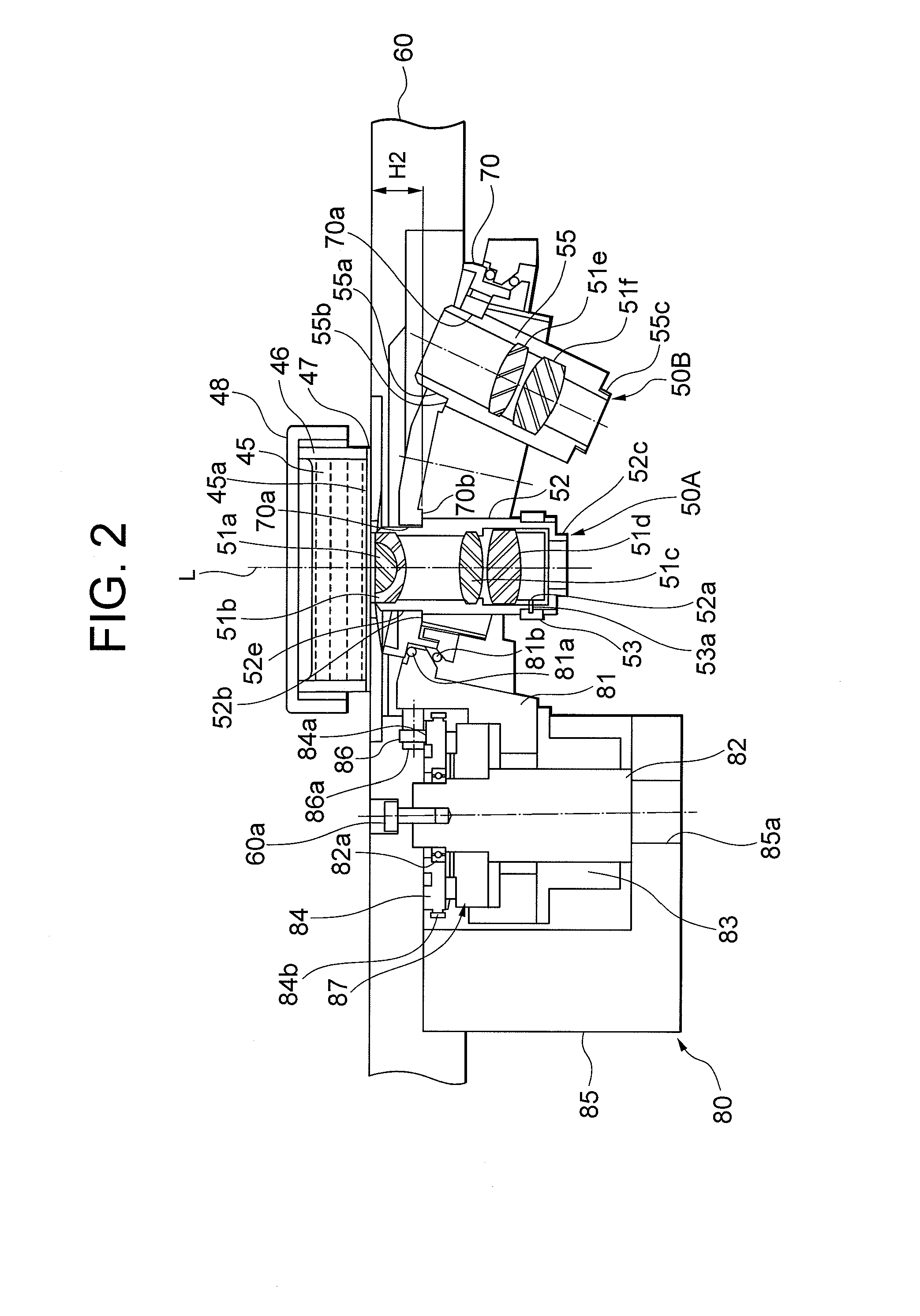
[0019]The inverted microscope includes a microscope main body 10, a lens tube 20, an illumination support 30, and a stage unit 40.

[0020]The illumination support 30 is provided on an end of the microscope main body 10.

[0021]The illumination support 30 is composed of a vertical portion 31 and a horizontal portion 32 extending horizontally from the upper end of the vertical portion 31. A lamp house 35 is provided on rear side of the upper end of the vertical portion 31, and a condenser lens 33 is provided on the horizontal portion 32 through a mounting portion 34. In the lamp house 35, such as a halogen lamp 36 is installed.

[0022]An epi-illumination fluorescence unit 90 for carrying out epi-illumination fluorescence observation is provided on re...


PUM


Abstract

An objective lens to be fitted into a fitting hole of a nosepiece of a microscope includes an imaging lens that is composed of a plurality of lens groups, and a lens barrel that holds the imaging lens. The lens barrel is formed with a fitting portion that is fitted to the fitting hole of the nosepiece and provided at an outer circumference of a tip portion side away by a given distance from the tip portion where a first lens group in the imaging lens is held, and a mount surface that comes into contact with a contact surface of the fitting hole of the nosepiece upon fitting at the fitting portion. The nosepiece is equipped with the objective lens. The inverted microscope is equipped with the nosepiece fitting the objective lens.

Description

TECHNICAL FIELD [0001]The present invention relates to an objective lens, a nosepiece and an inverted microscope equipped therewith.BACKGROUND ART[0002]In a conventional inverted microscope, a plurality of objective lenses, a nosepiece holding these objective lenses, and a nosepiece holder that is fixed to a stage and holds the nosepiece through a supporting member are disposed under the stage (see Japanese Patent Application Laid-Open No. 11-38326).[0003]A rack and pinion mechanism is provided between the nosepiece holder and the supporting member. With rotating a focusing knob provided on the nosepiece holder, the objective lens selectively provided on the optical path can be moved up and down so as to focus on a sample. The distance between the objective lens and the stage has to be kept to a distance between the objective lens and the sample upon focusing on the sample.DISCLOSURE OF THE INVENTION[0004]When an environment temperature of the microscope goes up by heat from a light...

Claims


Application Information

Patent Timeline
Patent Type & Authority Applications(United States)
IPC IPC(8): G02B21/02G02B7/02
CPCG02B21/0088G02B21/248G02B21/02
Inventor KAWAHITO, TAKASHI
Owner NIKON CORP
Why Eureka
Try Eureka