Flexible printed circuit board for use in surface-mount technology

Inactive Publication Date: 2010-04-15
CHI MEI COMM SYST INC
View PDF12 Cites 4 Cited by
  • Summary
  • Abstract
  • Description
  • Claims
  • Application Information

AI Technical Summary

Benefits of technology

[0005]Generally, the FPCs are connected to a rigid main board by a connector or by a process of thermal compression bonding. However, the use of the connector increases the volume and cost of electronic devices. The process of thermal compression bonding requires manual operation, decreasing the efficiency of assembly of electronic devices.

Problems solved by technology

However, the use of the connector increases the volume and cost of electronic devices.
The process of thermal compression bonding requires manual operation, decreasing the efficiency of assembly of electronic devices.
However, it is difficult to pack and precisely position the FPCs because the FPCs are flexible.

Method used


Image

  • Flexible printed circuit board for use in surface-mount technology
  • Flexible printed circuit board for use in surface-mount technology
  • Flexible printed circuit board for use in surface-mount technology

Examples


Embodiment Construction

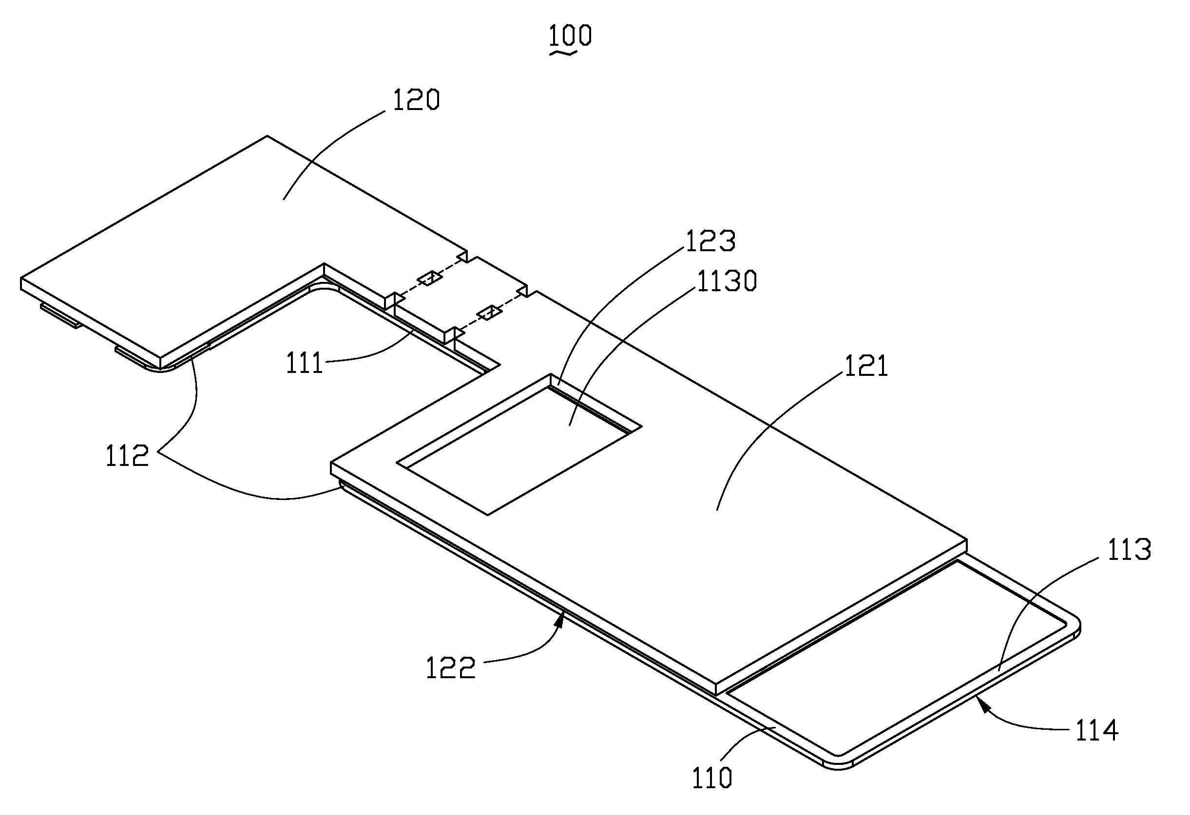
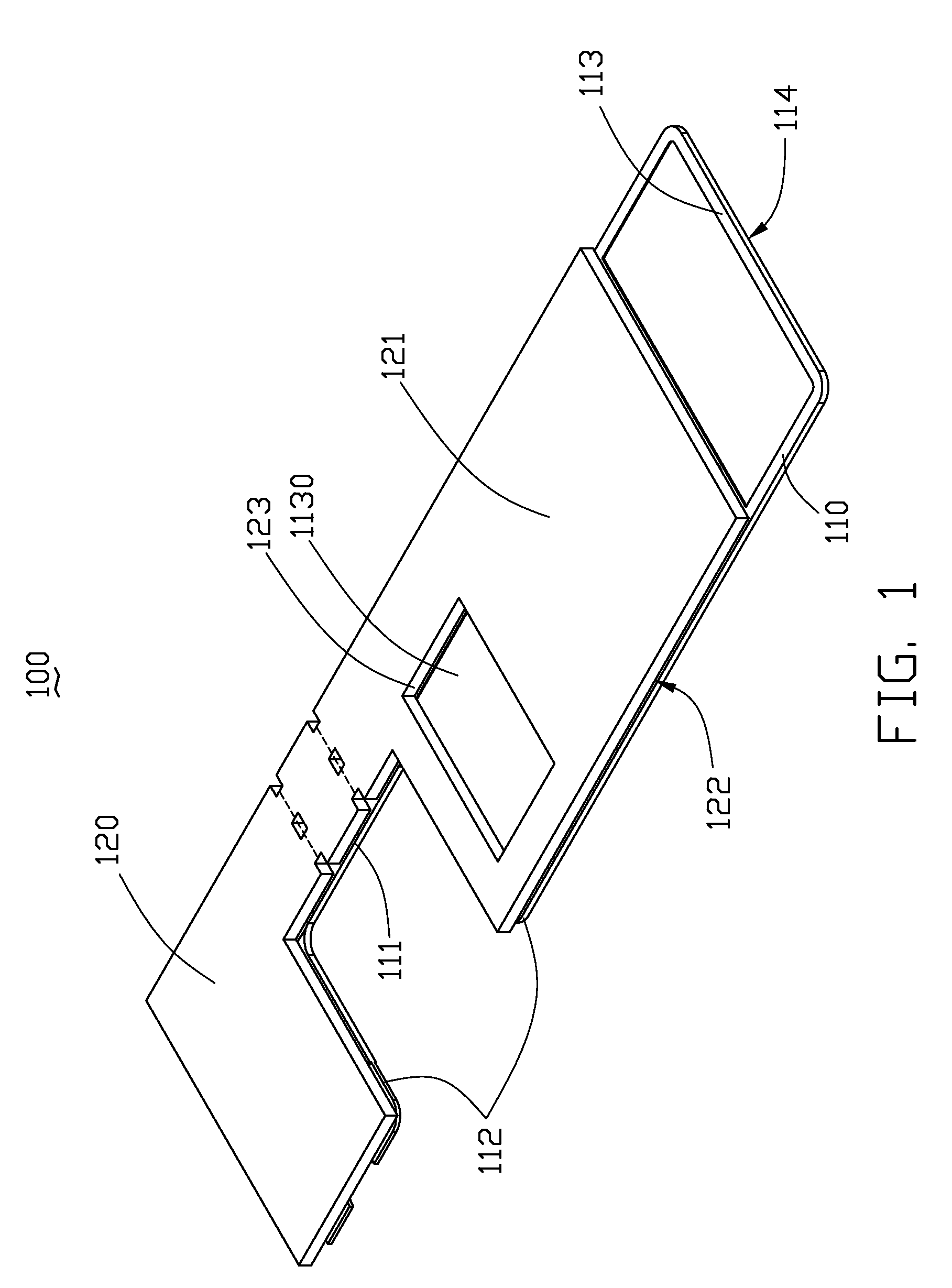
[0012]An FPC 100 includes a flexible sheet 110 and a rigid substrate 120. The flexible sheet 110 is wired and configured for electrically connecting to a main board 200. The rigid substrate 120 is attached to the flexible sheet 110 and configured for enhancing operability of the FPC 100 in SMT.

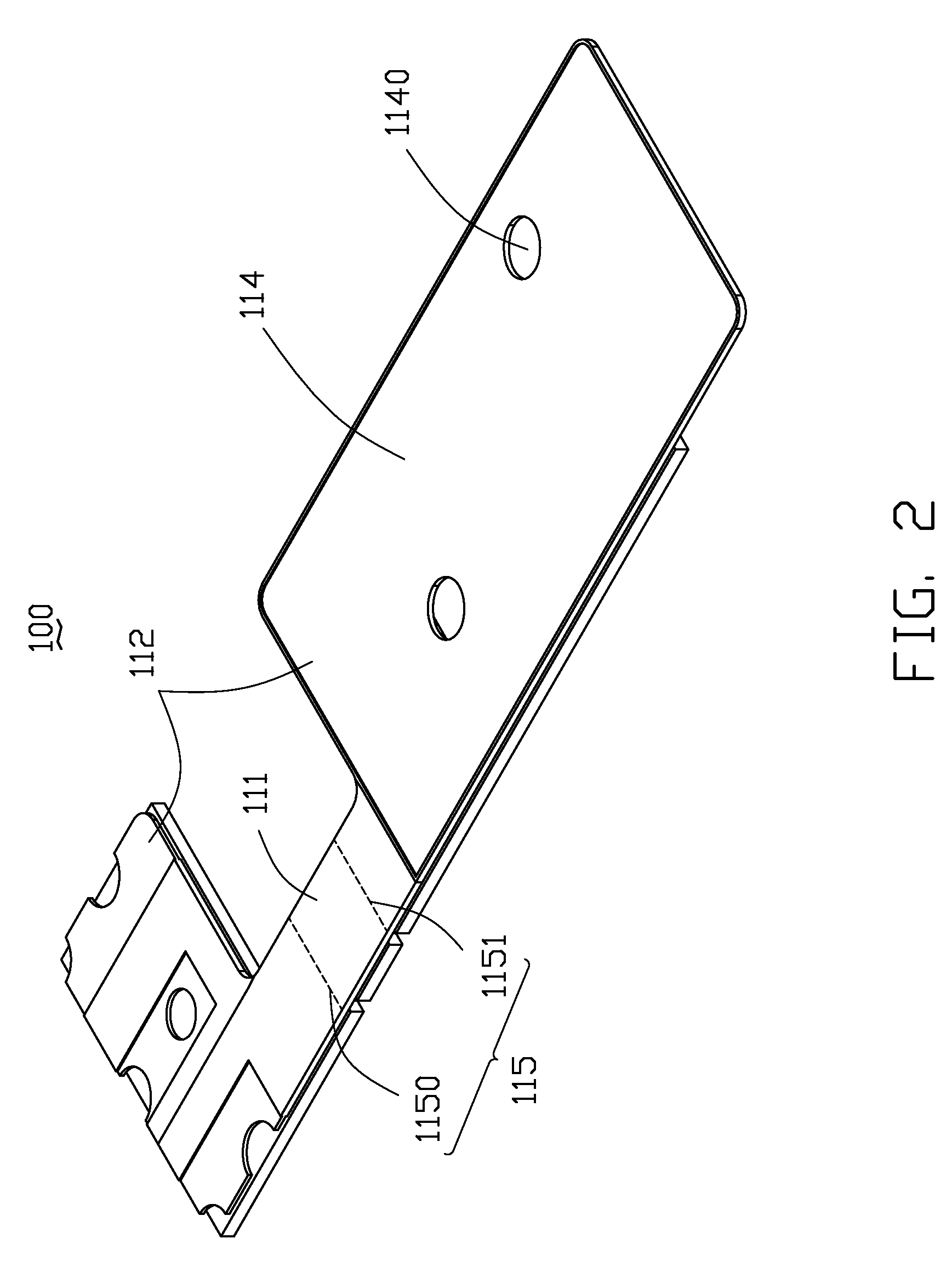
[0013]For purpose of illustration only, the flexible sheet 110 includes a bendable portion 111, a first surface 113, and an opposite second surface 114. The flexible sheet 110 also includes two connecting portions 112 interconnected by the bendable portion 111. The bendable portion 111 has two seams 115: a first seam 1150 and a second seam 1151. In this embodiment, the bendable portion 111 and the connecting portions 112 are integral formed.

[0014]One of the connecting portions 112 is configured for electrically connecting to the main board 200. The other connecting portion 112 is configured for electrically connecting to another board 201 that often lies in a different plane than the main boar...


PUM


Abstract

A flexible printed circuit board includes a flexible sheet and a rigid substrate attached to the flexible printed circuit board. The flexible printed circuit board includes a first surface and an opposite second surface. A number of electrical connecting locations are defined on the first surface of the flexible printed circuit. The rigid substrate includes a third surface and an opposite fourth surface and is disposed on the flexible sheet with the fourth surface contacting the first surface of flexible sheet. The rigid substrate defines a number of through holes corresponding to the electrical connecting location to allow the electronic components to pass through.

Description

BACKGROUND[0001]1. Technical Field[0002]The present disclosure relates to printed circuit boards (PCBs) and, particularly, to a flexible printed circuit board (FPC) which can be coupled to a rigid PCB using surface-mount technology (SMT).[0003]2. Description of Related Art[0004]FPCs are widely used in board-to-board or chip-to-board connections in electronic devices which require multi-dimension electrical connections, utilizing the flexibility of the FPCs[0005]Generally, the FPCs are connected to a rigid main board by a connector or by a process of thermal compression bonding. However, the use of the connector increases the volume and cost of electronic devices. The process of thermal compression bonding requires manual operation, decreasing the efficiency of assembly of electronic devices.[0006]To overcome the defects of above-mentioned methods, SMT is also considered. Commonly, if SMT is applied, the FPCs need to be packed up as tape and positioned to desired locations of the rig...

Claims


Application Information

Patent Timeline
IPC IPC(8): H05K1/14H05K1/00
CPCH05K1/148H05K1/189H05K3/0064H05K2203/063H05K2201/09036H05K2201/2009H05K3/363
Inventor TSAO, CHANG-WEI
Owner CHI MEI COMM SYST INC
Why Eureka
Try Eureka