Speaker device

Inactive Publication Date: 2010-04-15
PIONEER CORP +1
View PDF16 Cites 7 Cited by
  • Summary
  • Abstract
  • Description
  • Claims
  • Application Information

AI Technical Summary

Benefits of technology

[0016]According to the former speaker device, since the lead wire which supplies a drive signal to the voice coil is disposed along the surface shape of the edge portion which supports the drive cone which is integrally driven with the diaphragm. Therefore, the lead wire is deformed such as to follow the deformation of the edge portion of the drive cone in accordance with vibration of the diaphragm.
[0017]That is, since the lead wire follows the deformation of the edge portion which supports the drive cone, like the conventional structure in which the portion of the lead wire floats in the air, the lead wire freely deforms as it is vibrated, and a degree of the root portion on which the lead wire is mounted whic

Problems solved by technology

Therefore, it is difficult to provide the damper with high compliance, and in a damper of the speaker which secures a large amplitude stroke, there is a problem that nonlinearity of a movable load is brought about and power linearity is deteriorated.
In addition, there is also a problem that mechanical fatigue of the damper is generated faster than that of the edge portio

Method used


Image

  • Speaker device
  • Speaker device
  • Speaker device

Examples


first embodiment

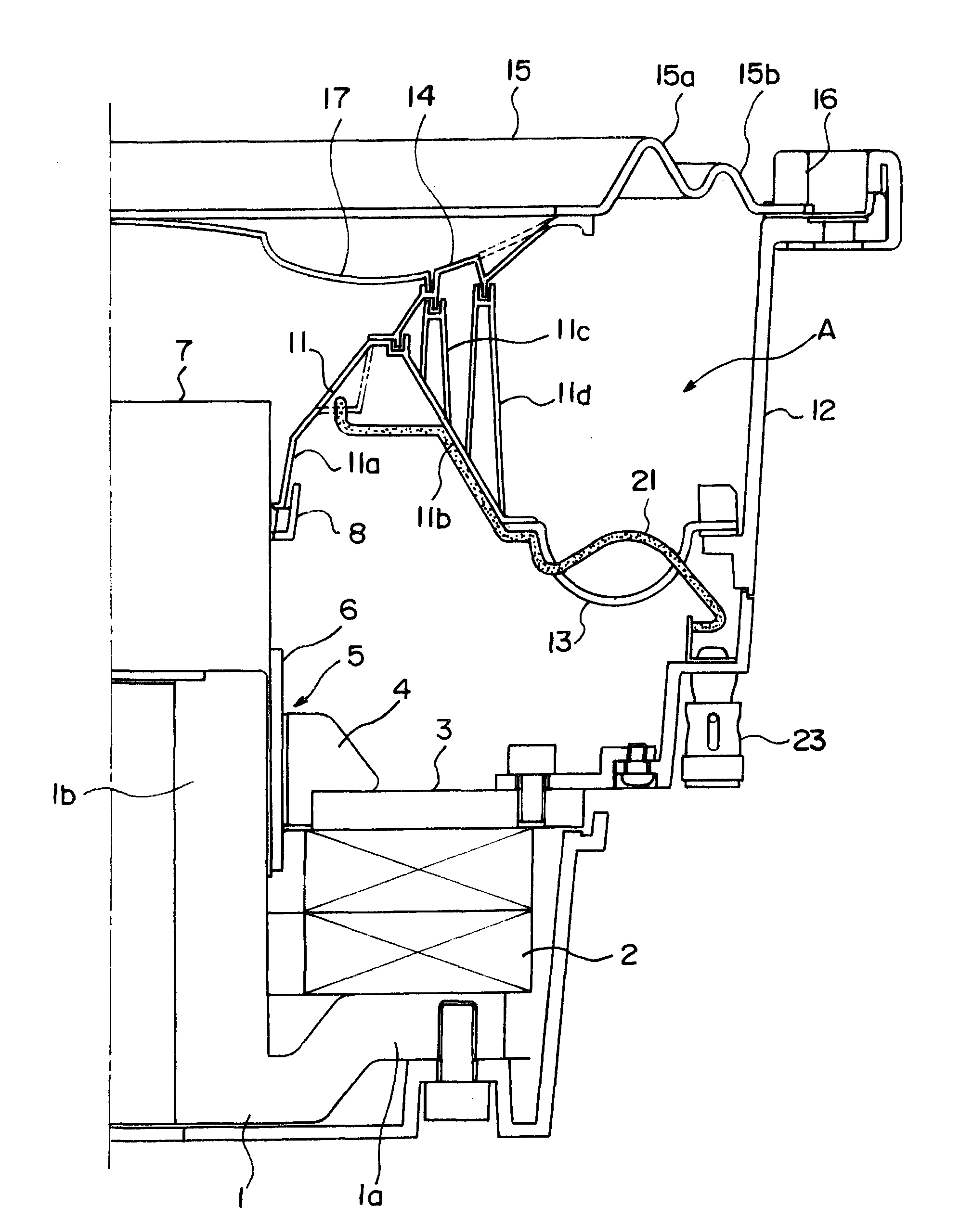
[0046]A speaker device according to the present invention will be explained based on embodiments illustrated in the drawings. FIG. 1 shows the first embodiment, and is a sectional view of a right half of the speaker device from its center line. A reference numeral 1 represents a pole yoke whose center portion is a hollow. A disk-like flange 1a is integrally formed on a bottom of the pole yoke 1, ring-like magnets 2 are mounted on the flange 1a coaxially with a cylindrical portion 1b of the pole yoke 1.

[0047]A ring plate 3 is mounted on an upper surface of the magnet 2, and a ring sub plate 4 is mounted such that it is fitted to the inner peripheral surface of the plate 3. With this structure, a magnetic gap 5 is formed between the inner peripheral surface of the ring sub plate 4 and the outer peripheral surface of the pole yoke 1 (outer peripheral surface of the cylindrical portion 1b).

[0048]A cylindrical coil bobbin 7 around which a voice coil 6 is wound is mounted in the magnetic ...

fourth embodiment

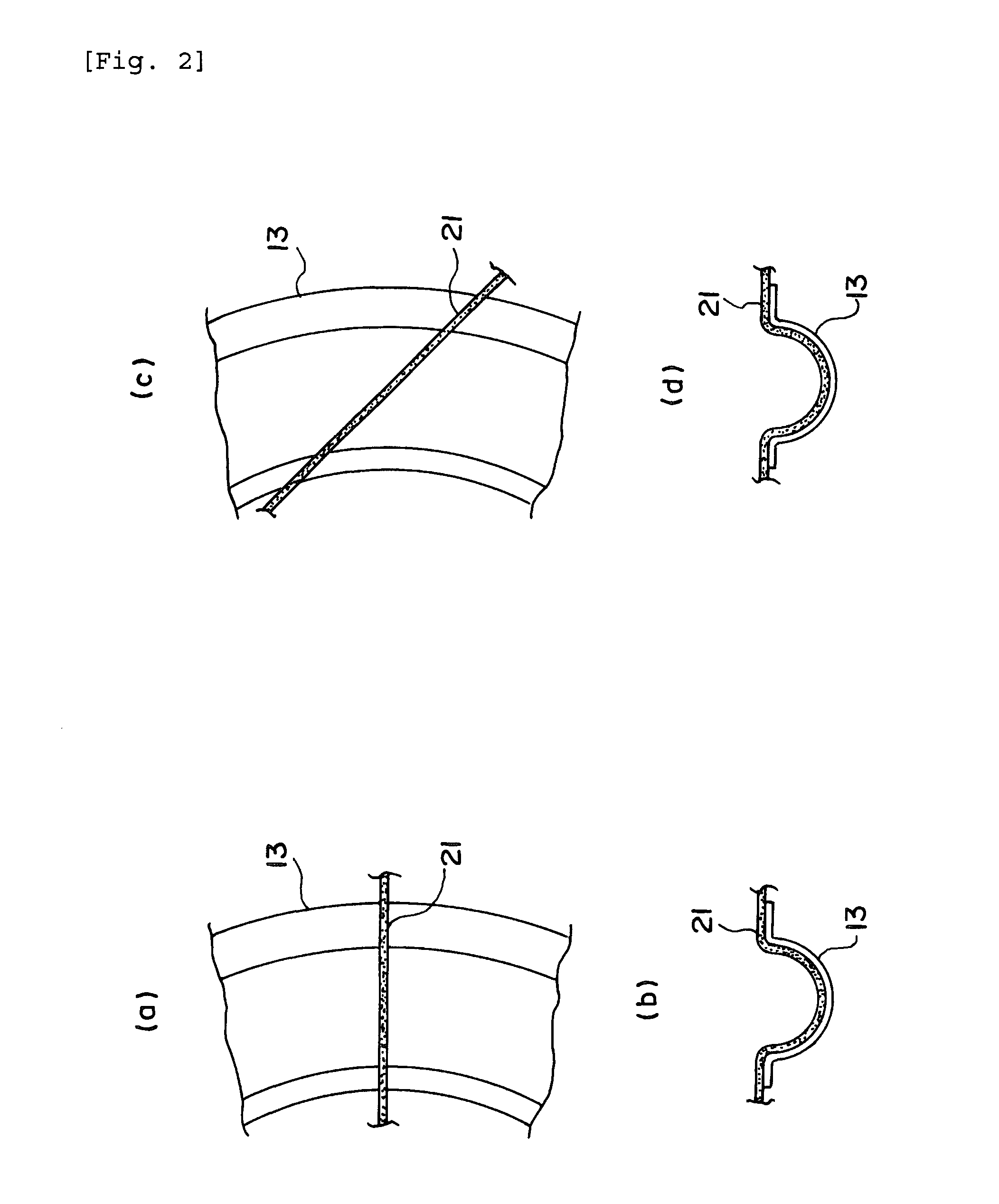
[0065]FIGS. 3(c) and (d) show a forth example thereof, (c) shows a layout state of the lead wire 21 in which the edge portion 13 is viewed from above, and (d) shows a layout state of the lead wire 21 as viewed from a direction of an end surface of a state where the edge portion 13 is cut in the normal direction. In the fourth embodiment, a groove 13a in which a portion of the lead wire 21 can be accommodated is formed in the edge portion 13 in the direction of the normal. A portion of the lead wire 21 extending along the roll shape of the edge portion is accommodated in the groove 13a.

second embodiment

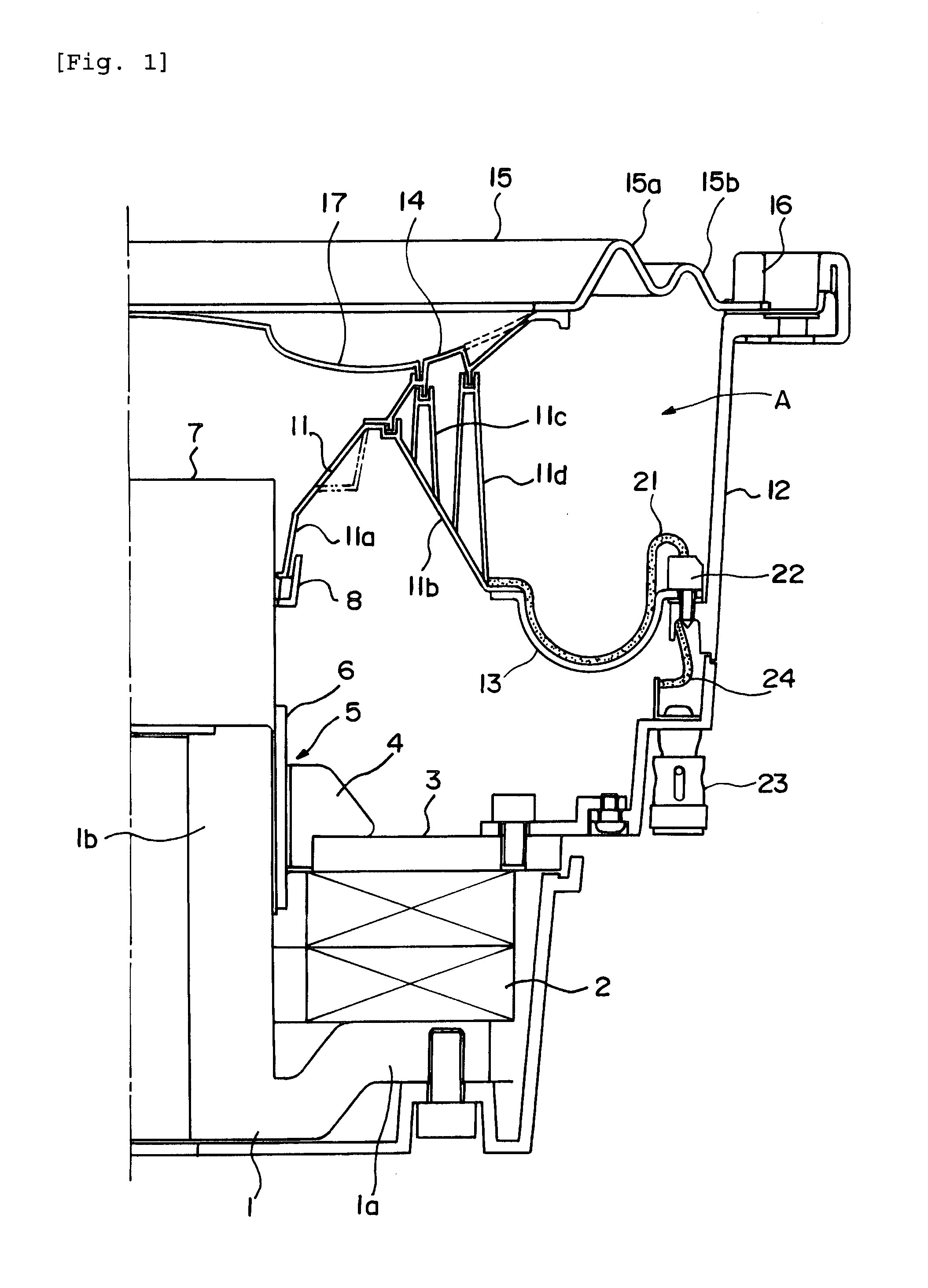
[0066]FIG. 4 shows the speaker device of the present invention. Like FIG. 1, FIG. 4 is a sectional view of a right half from the center line of the speaker device. The basic structure of the speaker shown in FIG. 4 is the same as that of the already explained speaker shown in FIG. 1, the corresponding parts are designated with the same reference numerals, and detailed explanation thereof will be omitted.

[0067]The structure of the speaker shown in FIG. 4 is different from that shown in FIG. 1 in that the roll shape of the edge portion 13 which supports the peripheral edge of the drive cone 11 is curved upward, i.e., toward the hermetic space A. In the edge portion 13 having the upper roll shape as shown in FIG. 4, the layout states of the lead wire 21 as shown in FIGS. 2 and 3 can also appropriately be employed.


PUM


Abstract

A drive cone 11 and a diaphragm 14 are integrally driven by a voice coil 6 which is movably disposed in a magnetic gap 5. Peripheral edges of the drive cone 11 and diaphragm 14 are supported by a frame 12 through edge portions 13 and 15.
A lead wire 21 supplies a drive signal to the voice coil 6. The lead wire 21 is disposed along a surface shape of the edge portion 13 which supports the drive cone 11. The lead wire 21 is mounted along a roll shape of a flexible adhesive utilizing the adhesive.
With this structure, the lead wire 21 deforms such as to follow deformation of the edge portion 13 in the drive cone 11 in accordance with vibration of the diaphragm 14. Therefore, it is possible to prevent a bending stress caused by vibration from being transmitted to a portion of the lead wire.

Description

TECHNICAL FIELD [0001]The present invention relates to a dynamic type speaker device, and more particularly, to an improvement of a layout structure of an electric supply line (lead wire) for supplying a drive signal to a voice coil.BACKGROUND TECHNIQUE [0002]In the dynamic type speaker, basically, a bobbin around which a voice coil is wound is mounted in an inner periphery of a cone type diaphragm, an outer periphery and the inner periphery of the diaphragm are mounted on a frame through an edge portion and a damper, respectively. That is, the edge portion and the damper constitute a suspension of a vibration system.[0003]In a deep bass reproducing speaker so-called woofer or sub woofer utilized in a vehicular audio system, for example, since a diameter of the diaphragm is limited, an amplitude stroke of the diaphragm is increased so that a sufficient sound pressure level of bass can be secured.[0004]The damper which constitutes the suspension of the vibration system must have a fu...

Claims


Application Information

Patent Timeline
IPC IPC(8): H04R9/06
CPCH04R1/06H04R2499/13H04R31/006H04R9/06
Inventor KAIYA, TERUAKI
Owner PIONEER CORP
Why Eureka
Try Eureka