Developing cartridge and image forming apparatus using the same

a development cartridge and cartridge technology, applied in the direction of electrographic process equipment, instruments, optics, etc., can solve the problems of cartridge, developing cartridge, or image forming equipment malfunction, and achieve the effect of preventing leakage of developer

Active Publication Date: 2010-04-15
SHARP KK
View PDF1 Cites 16 Cited by
  • Summary
  • Abstract
  • Description
  • Claims
  • Application Information

AI Technical Summary

Benefits of technology

[0008]In view of the above-described circumstances, the present invention provides a developing cartridge capable of preventing such a malfunction caused when the cartridge is mounted on an image forming apparatus, and an image forming apparatus using the cartridge.
[0010]According to the present invention, the leakage of developer can be prevented against vibration during transportation, because the shutter is maintained in a closed state by the electrically-releasing adhesive. Also, malfunctions caused by mounting the developing cartridge on an image forming apparatus without removing a sealing member of the developing cartridge can be prevented, because the shutter can be used instead of the sealing member and opened by supplying an electric current to the electrically-releasing adhesive when the cartridge is mounted.

Problems solved by technology

However, some users carelessly mount such a cartridge on the image forming apparatus without removing the sealing member, which causes a malfunction to the cartridge, the developing cartridge, or the image forming apparatus.

Method used


Image

  • Developing cartridge and image forming apparatus using the same
  • Developing cartridge and image forming apparatus using the same
  • Developing cartridge and image forming apparatus using the same

Examples


embodiment 1

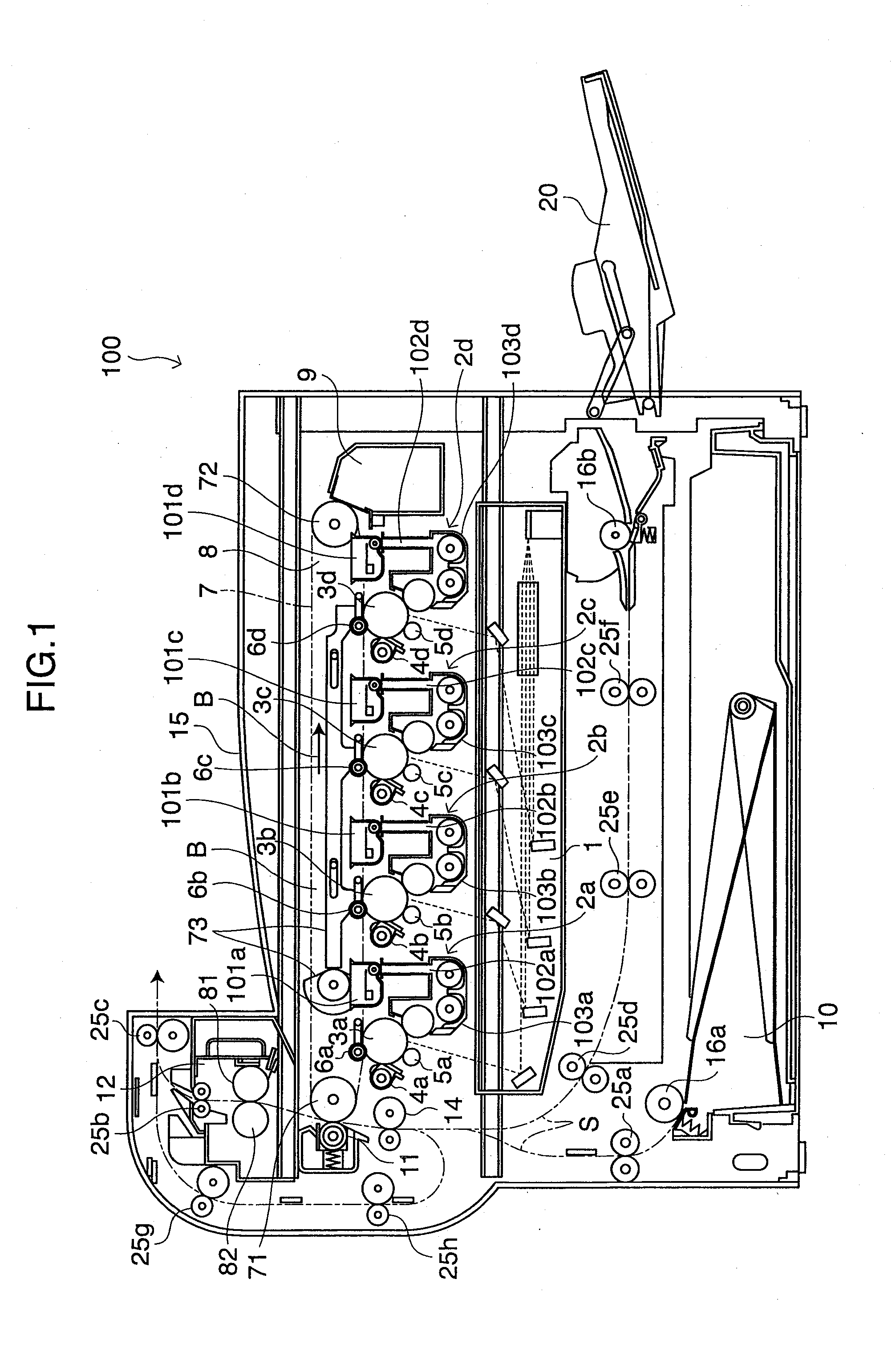
[0039]FIG. 1 is an explanatory diagram illustrating an internal configuration of an image forming apparatus 100 according to Embodiment 1 of the present invention.

[0040]The image forming apparatus 100 is a printer of an electrophotographic system, and it forms a multicolor or monochrome image on a predetermined sheet (recording paper, recording medium) according to image data transmitted from an external. Here, a scanner or the like may be provided in an upper part of the image forming apparatus 100.

[0041]In the image forming apparatus 100, image data of black (K), cyan (C), magenta (M), and yellow (Y) color components are handled individually, and a black image, a cyan image, a magenta image, and a yellow image are formed and the images of each color component are superimposed to form a color image. Therefore, developing devices 2a, 2b, 2c, 2d, photosensitive drums 3a, 3b, 3c, 3d, chargers 5a, 5b, 5c, 5d, and cleaner units 4a, 4b, 4c, 4d are provided in the image forming apparatus ...

embodiment 2

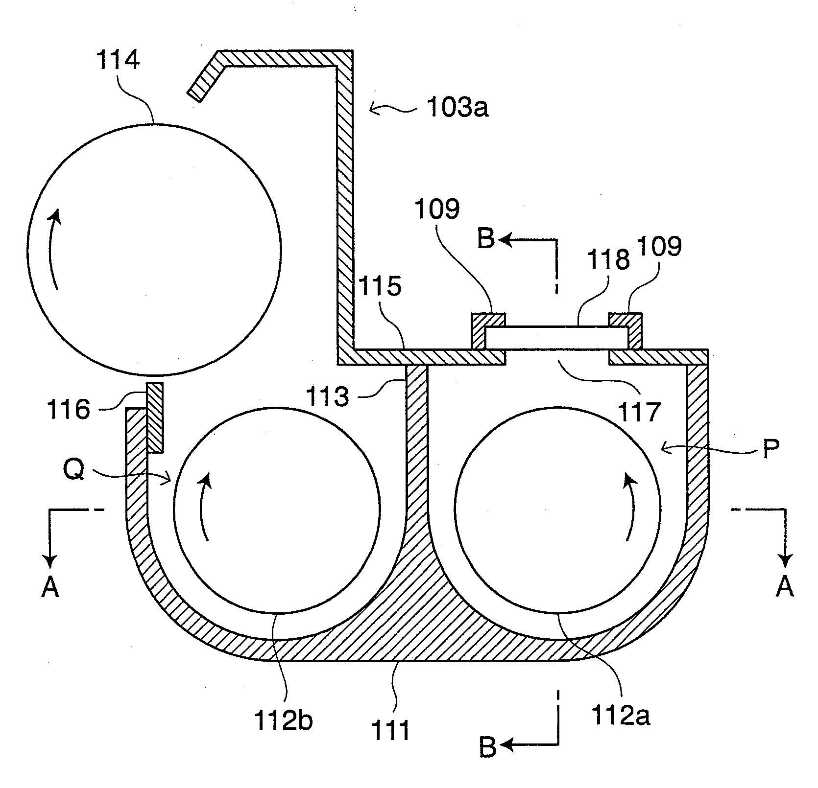
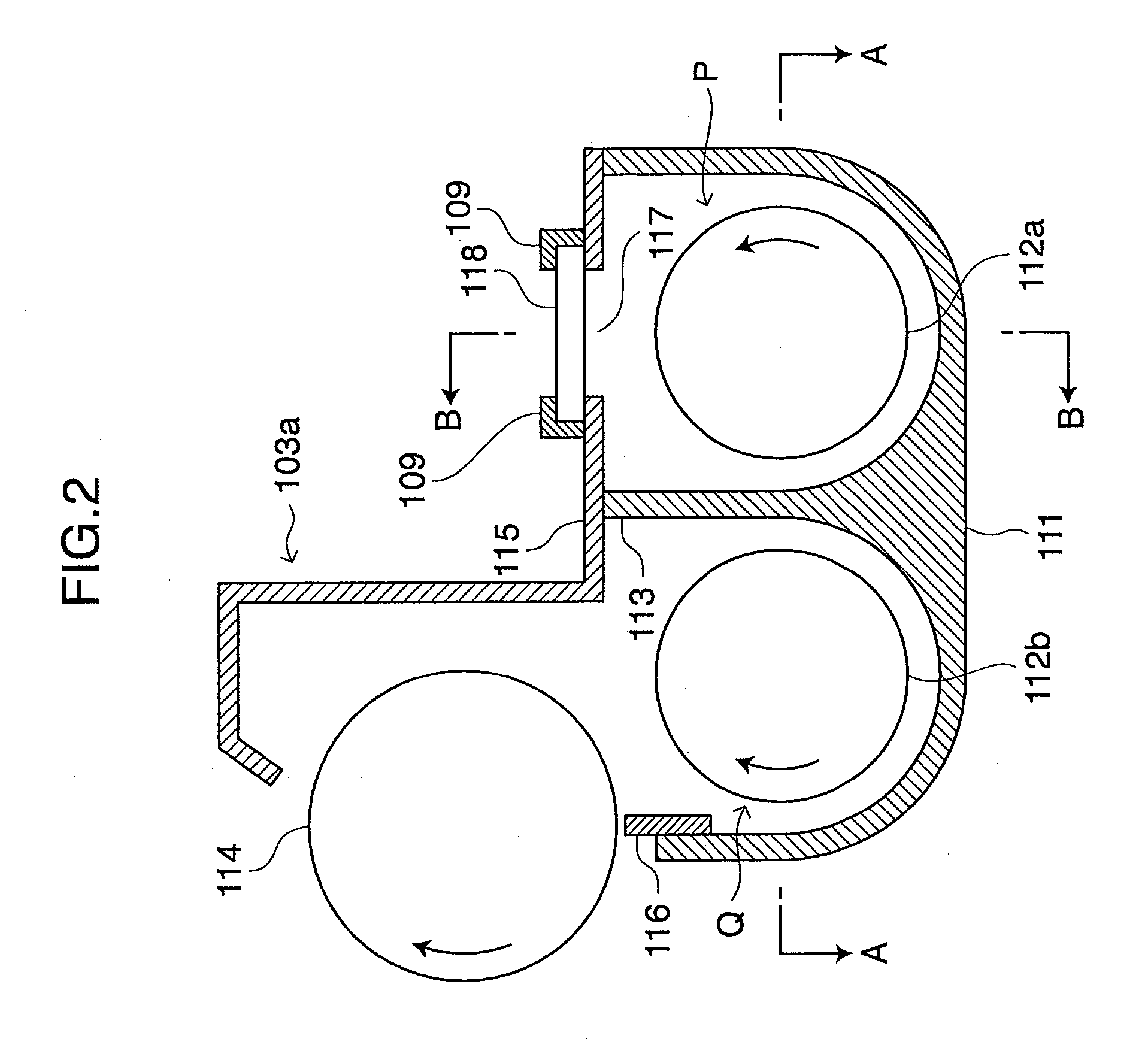
[0100]FIG. 11 is an explanatory diagram illustrating an internal configuration of an image forming apparatus 230 according to Embodiment 2 of the present invention. The image forming apparatus 230 comprises: a toner supplying device bearing developing cartridge (hereinafter, referred to as toner cartridge) 210, a photosensitive drum 217, a charging device 225, an exposure device 222, a cleaning device 226, a transfer device 224, a fixing device 223, a sheet feeding cassette 221, a sheet exit tray 229, and a scanner unit 231.

[0101]The photosensitive drum 217 is supported by a driving means, not shown, so that it can be driven rotationally around an axis. And, the photosensitive drum 217 is a roller-shaped member having a photosensitive drum having a surface on which an electrostatic latent image, eventually a toner image, is formed. As the photosensitive drum 217, for example, a roller-shaped member that includes a conductive substrate, not shown, and a photosensitive drum, not shown...


PUM


Abstract

A developing cartridge includes: a developing roller for developing an electrostatic latent image of a photoconductor with a toner; and a developing tank for storing the toner to be supplied to the developing roller, the developing tank including: a toner receiving port for receiving the toner to be stored; a shutter having a function for sliding to open and close the toner receiving port, the shutter being adapted to be maintained in a closed state by an electrically-releasing adhesive; and a pair of conductive member for supplying an electric current to the electrically-releasing adhesive to open the shutter.

Description

CROSS-REFERENCE TO RELATED APPLICATIONS[0001]This application is related to Japanese Patent Applications Nos. 2008-264026 filed on Oct. 10, 2008 and 2009-094858 filed on Apr. 9, 2009, whose priorities are claimed under 35 USC §119, and the disclosures of which are incorporated by reference in their entirety.BACKGROUND OF THE INVENTION[0002]1. Field of the Invention[0003]The present invention relates to a developing cartridge and an image forming apparatus using the same.[0004]2. Description of the Related Art[0005]As for conventional image forming apparatuses such as copying machines and laser printers which employ electrophotographic systems, it has been a trend that toner cartridges or developing cartridges can be replaced by users themselves for improvement of convenience for the users. While such cartridges are usually replaced when the toner runs out, many cartridges are to be replaced when the cumulative number of printed sheets or the cumulative time of use reaches a predeter...

Claims


Application Information

Patent Timeline
Patent Type & Authority Applications(United States)
IPC IPC(8): G03G15/06
CPCG03G2215/0687G03G2215/0692G03G15/0875G03G15/0882G03G15/0893G03G15/0877G03G15/0886
Inventor MIMURA, SHINYA
Owner SHARP KK
Why Eureka
Try Eureka