Electrical connector for electrical communication between a power cable and an electrical device

a technology of electrical communication and electrical connector, which is applied in the direction of coupling device connection, coupling device details, contact members penetrating/cutting insulation/cable strands, etc., can solve the problems of higher production cost and complicated electrical connector, and achieve convenient use, avoid accidental disconnection, and avoid accidental disconnection

Inactive Publication Date: 2010-04-15
CHECKSON DIE CASTING & PROD FACTORY
View PDF14 Cites 17 Cited by
  • Summary
  • Abstract
  • Description
  • Claims
  • Application Information

AI Technical Summary

Benefits of technology

[0017]The advantages of the present invention are that in comparison with the prior art the present invention is more convenient to use as no screws are required and the plug of the electrical device may simply be plugged into the receptacle. The connecting member of the present invention can effectively avoid the cap from being misplaced or otherwise lost. The fastening ring can cover a section of the cable of the electrical device after its plug is being plugged into the receptacle for avoiding accidental disconnection and for making the connection weatherproof. The connection of the cap with the housing by means of screwing can also avoid accidental disconnection and make the connection weatherproof. This construction highly increases the safety level and the present invention is therefore adapted for use with a high voltage power source as well unlike the prior art.

Problems solved by technology

However, the said improved electrical connector is more complicated in construction having more parts and components and is therefore susceptible of higher production costs.
Further, both the conventional electrical connector and the said improved electrical connector are only adapted for use with power sources of low voltage electricity.

Method used


Image

  • Electrical connector for electrical communication between a power cable and an electrical device
  • Electrical connector for electrical communication between a power cable and an electrical device
  • Electrical connector for electrical communication between a power cable and an electrical device

Examples


Embodiment Construction

[0033]The preferred embodiments of the present invention are further described in detail with the following embodiments and the accompanying drawings.

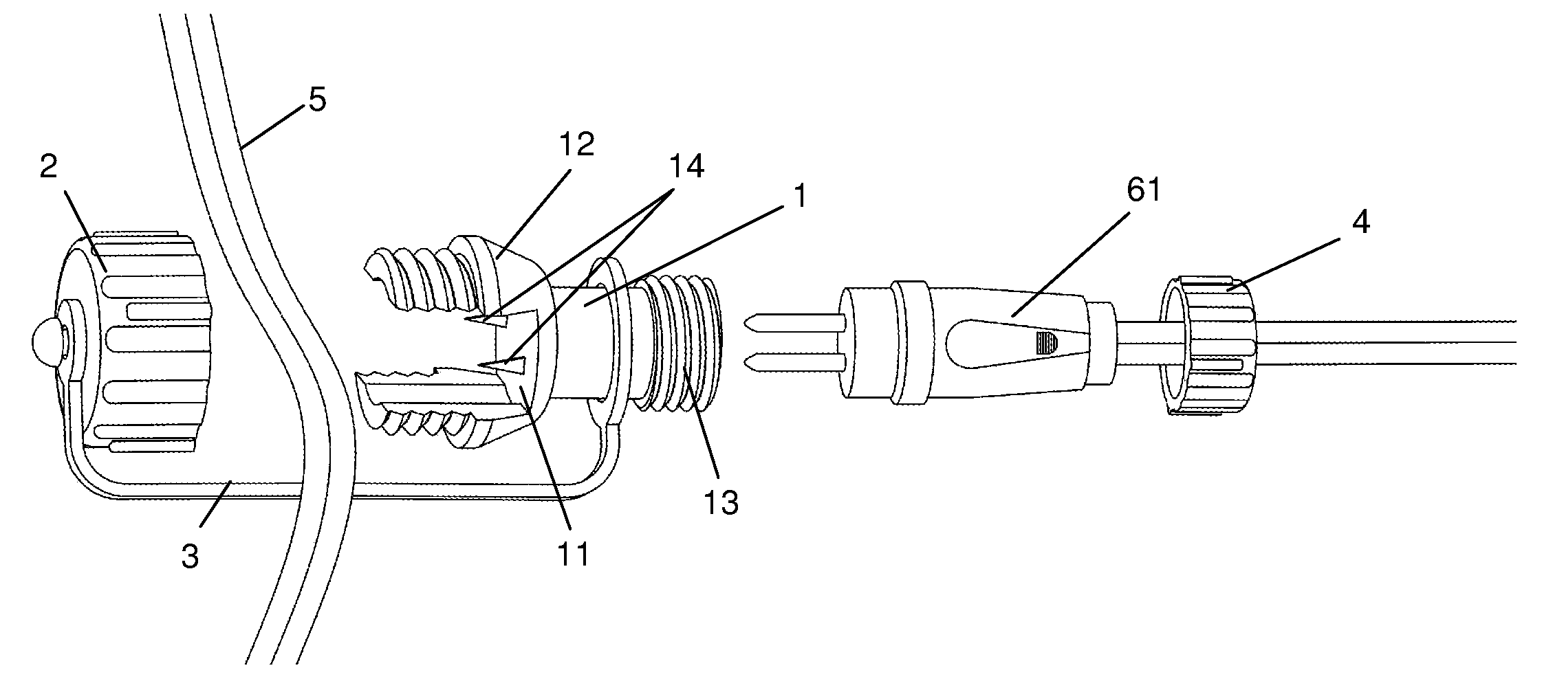
[0034]FIGS. 3 to 10 illustrates the construction of an electrical connector of the first embodiment of the present invention. The electrical connector of the present invention is for electrical communication between a power cable 5 and an electrical device 6 and it comprises a tubular housing 1, one end of which having a longitudinal channel 11 for receiving the power cable 5 as defined by the flanges 12 one on each side having a threaded radically outward surface, and the other end of which having a receptacle 13 for receiving a two-pin plug 61 of the electrical device 6 and after plugging the two electrically conductive contacts of the plug 61 each connects to two stabs 14 which are electrically conductive and extend from the channel 11 for piercing the power cable 5; and a cap 2 having a threaded interior surface for engaging with t...


PUM


Abstract

An electrical connector for electrical communication between a power cable and an electrical device comprising a tubular housing, one end of which having a longitudinal channel for receiving the power cable as defined by the flanges one on each side having a threaded radically outward surface, and the other end of which having a receptacle for receiving a two-pin or three-pin plug of the electrical device and after plugging the two electrically conductive contacts of the plug each connects to one or more stabs which are electrically conductive and extend from the channel for piercing the power cable; and a cap having a threaded interior surface for engaging with the threaded outward surfaces of the flanges and having a pressing member attached onto the interior bottom surface of the cap for being received within the channel for pressing against the cable in the channel. The present invention is convenient to use and is adapted for use with a low voltage or high voltage power source.

Description

BACKGROUND OF THE INVENTION[0001]The present invention relates to electrical connectors and more particularly pertains to electrical connectors which are used to connect multiple electrical devices to a power cable without stripping the cable insulation or soldering the wires of the cable and the electrical devices together such that the power cable transmits power from a power source to the electrical devices.[0002]In general, these electrical connectors are used for outdoor lighting. An outdoor lighting system may be built with a number of these electrical connectors which connect to a cable for electrical communication and the cable connects to a power source such as an outdoor electrical socket, and each electrical connector connects to an outdoor lighting fixture. For safety, the lighting fixtures are low voltage lights and a transformer that changes high voltage power to low voltage power is connected in between the power source and the cable to turn the system into a low volt...

Claims


Application Information

Patent Timeline
Patent Type & Authority Applications(United States)
IPC IPC(8): H01R4/24
CPCH01R4/2408H01R13/59H01R13/622H01R2103/00H01R24/76H01R25/003H01R24/28
Inventor CHUEN, TSANG HON
Owner CHECKSON DIE CASTING & PROD FACTORY
Why Eureka
Try Eureka