
Adaptive iip2 calibration

a technology of iip2 and calibration, applied in the field of radio frequency receivers, can solve problems such as leaking into the receiver, problems that can adversely affect the performance of the receiver, and reducing so as to achieve the effect of reducing the sensitivity of the receiver, and reducing the transmission loss

Inactive Publication Date: 2010-04-15
NORTH STAR INNOVATIONS
View PDF19 Cites 51 Cited by
  • Summary
  • Abstract
  • Description
  • Claims
  • Application Information

AI Technical Summary

Problems solved by technology

If the LNA and the SAW filter are removed from the analog line-up of the receiver, problems that can detrimentally affect the performance of the receiver may arise.
In a transceiver, which comprises a transmitter and a receiver, one such problem is a signal transmitted by the transmitter leaking into the receiver.
Without a sufficiently high IP2 of the mixer, the presence of second-order intermodulation distortion (IMD2) substantially reduces the sensitivity of the receiver.
The IMD2 results from an unwanted squaring of the transmitted signal at the mixer of the receiver.
When the receiver is at sensitivity and the transmitter is at maximum output power, the self-blocking effect of the transmitter can, through a second-order nonlinearity of the mixer, desensitize the receiver.
This −25 dBm signal creates strong IMD2 products that land on the desired signal, thus producing interference.
The mismatch can be due to variations in manufacturing processes or due to temperature changes during operation of the receiver, or due to both causes.
The mismatch can also occur due to direct current (DC) offset, local oscillator leakage, or other factors.

Method used


Image

  • Adaptive iip2 calibration
  • Adaptive iip2 calibration
  • Adaptive iip2 calibration

Examples


Embodiment Construction

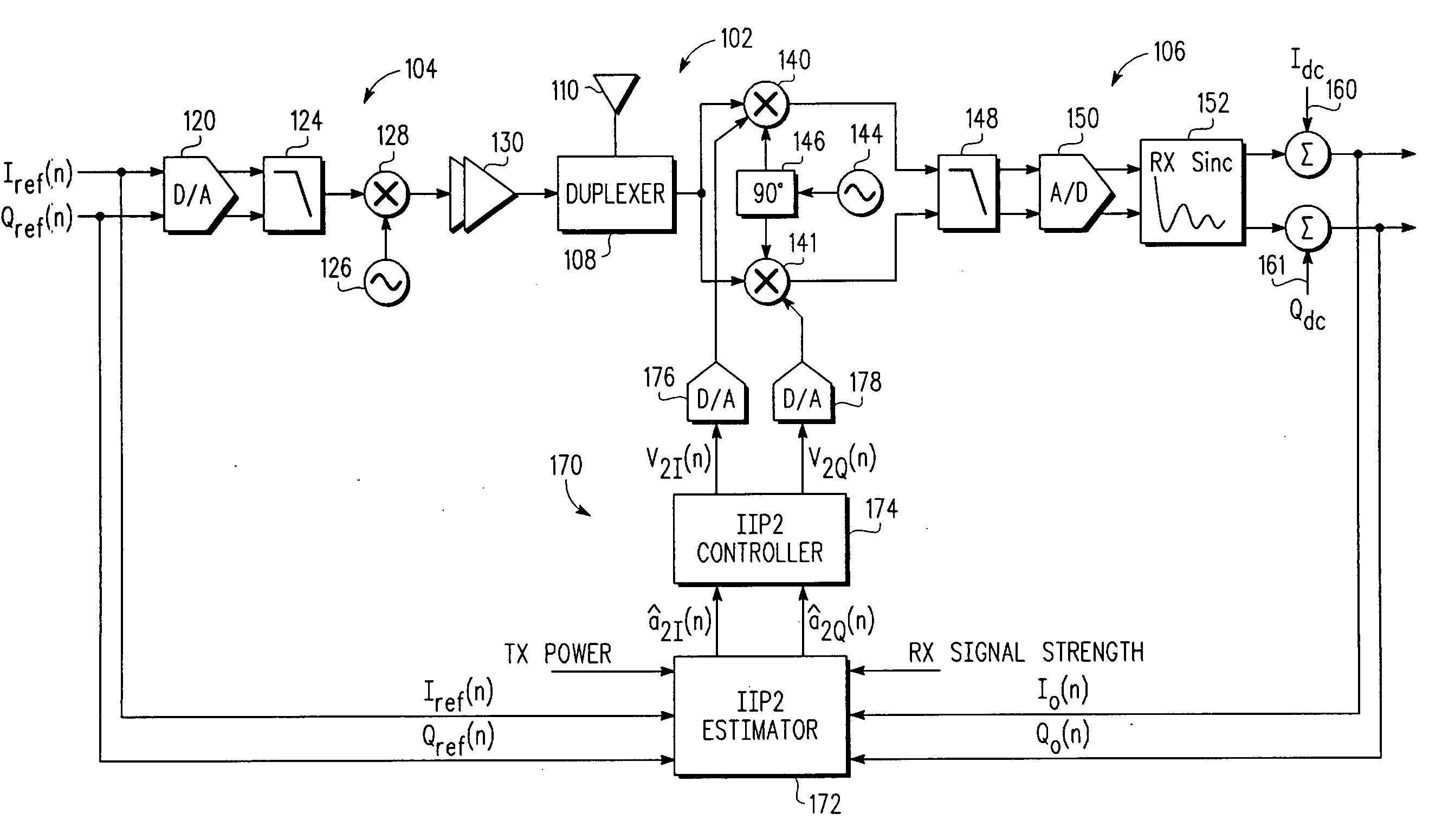
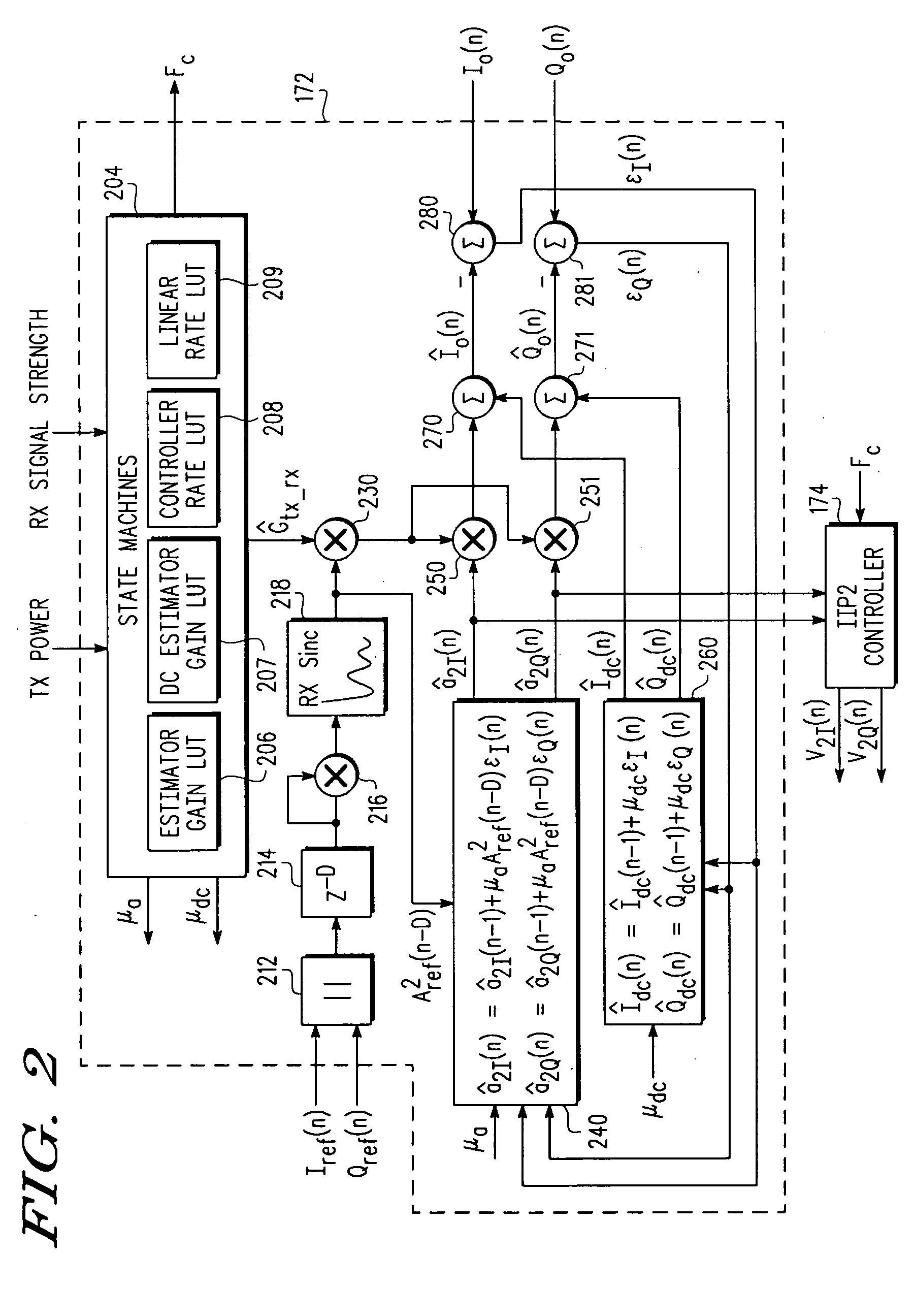
[0018]FIG. 1 illustrates a simplified functional block diagram of portions of a direct-conversion transceiver 102 that includes a portion of a transmitter 104 and a portion of a receiver 106. The transmitter 104 and the receiver 106 share a duplexer 108 and an antenna 110. The transmitter 104 includes a reference transmit baseband signal comprising an I-channel reference signal Iref and a Q-channel reference signal Qref outputted from another portion (not shown) of the transmitter. The I-channel reference signal Iref and the Q-channel reference signal Qref are fed into a respective digital-to-analog (D / A) converter 120. For simplicity of illustration, only one schematic symbol is shown in FIG. 1 for the D / A converter 120 and for several other components that occur in pairs in the I-channel and Q-channel signal paths of the transmitter 104 and the receiver 106. The output from the D / A converter 120 is fed into an analog lowpass filter 124. The transmitter includes a transmit oscillat...


PUM


Abstract

A radio frequency transceiver (102), including a transmitter (104), a duplexer (108) and a direct-conversion receiver (106) including a mixer (140 and 141). An IIP2 calibration system (170), coupled to the transceiver, includes an IIP2 coefficient estimator (172) for calculating an estimate of second-order distortion intermodulation distortion, and an IIP2 controller (174) for adjusting an IIP2 tuning port of the mixer in the receiver to minimize second-order distortion intermodulation distortion in the receiver that may be caused by the receiver receiving a transmit RF signal leaking through the duplexer.

Description

BACKGROUND OF THE INVENTION[0001]1. Field of the Invention[0002]This invention relates generally to radio frequency receivers, and more specifically to reducing second-order intermodulation distortion in a direct-conversion receiver.[0003]2. Related Art[0004]A radio frequency (RF) receiver uses the frequency response of a low noise amplifier (LNA), a surface acoustic wave (SAW) filter and a duplexer to attenuate signals that are far from a center frequency of the receiver sufficiently enough to not corrupt a desired signal. If the LNA and the SAW filter are removed from the analog line-up of the receiver, problems that can detrimentally affect the performance of the receiver may arise. In a transceiver, which comprises a transmitter and a receiver, one such problem is a signal transmitted by the transmitter leaking into the receiver. In a transceiver having only a duplexer to isolate the receiver from the transmitter, there is considerably less attenuation in the receiver of signals...

Claims


Application Information

Patent Timeline
IPC IPC(8): H04B17/00H04B1/06H04B1/26
CPCH04B17/21H04B1/109
Inventor PRATT, PATRICKSOBCHAK, CHARLES LEROY
Owner NORTH STAR INNOVATIONS
Learn More