Power transmission device

a transmission device and power technology, applied in the direction of gearing, dynamo-electric machines, dynamo-electric components, etc., can solve the problems of difficult miniature design implementation, large noise, unsmooth operation, etc., and achieve the effect of improving the reduction ratio and the torque within a limited spa

Inactive Publication Date: 2010-04-15
METAL INDS RES & DEV CENT
View PDF11 Cites 4 Cited by
  • Summary
  • Abstract
  • Description
  • Claims
  • Application Information

AI Technical Summary

Benefits of technology

[0010]In order to achieve the above objectives, a power transmission device is provided in the present invention, which includes a first motor, a first intermediate gearset, and a first planetary gearset assembly. The first motor has a motor output shaft. The first intermediate gearset has a first input gear connected to the motor output shaft. The first motor drives a first intermediate gear output shaft of a first output gear of the first intermediate gearset. The first planetary gearset assembly has an input end connected to the first intermediate gear output shaft. The first intermediate gear output shaft drives a planetary gear output shaft of an output end of the first planetary gearset assembly. To sum up, the power transmission

Problems solved by technology

In this case, the intermediate gearset is seldom used, because it occupies more space for the same reduction ratio and is difficult to implement the miniature design.
When more planetary gearsets 21 are used, the planetary gearset assembly 20 becomes more difficult to be assembled, and it further difficult to guarantee the concentricity of t

Method used


Image

  • Power transmission device
  • Power transmission device
  • Power transmission device

Examples


Embodiment Construction

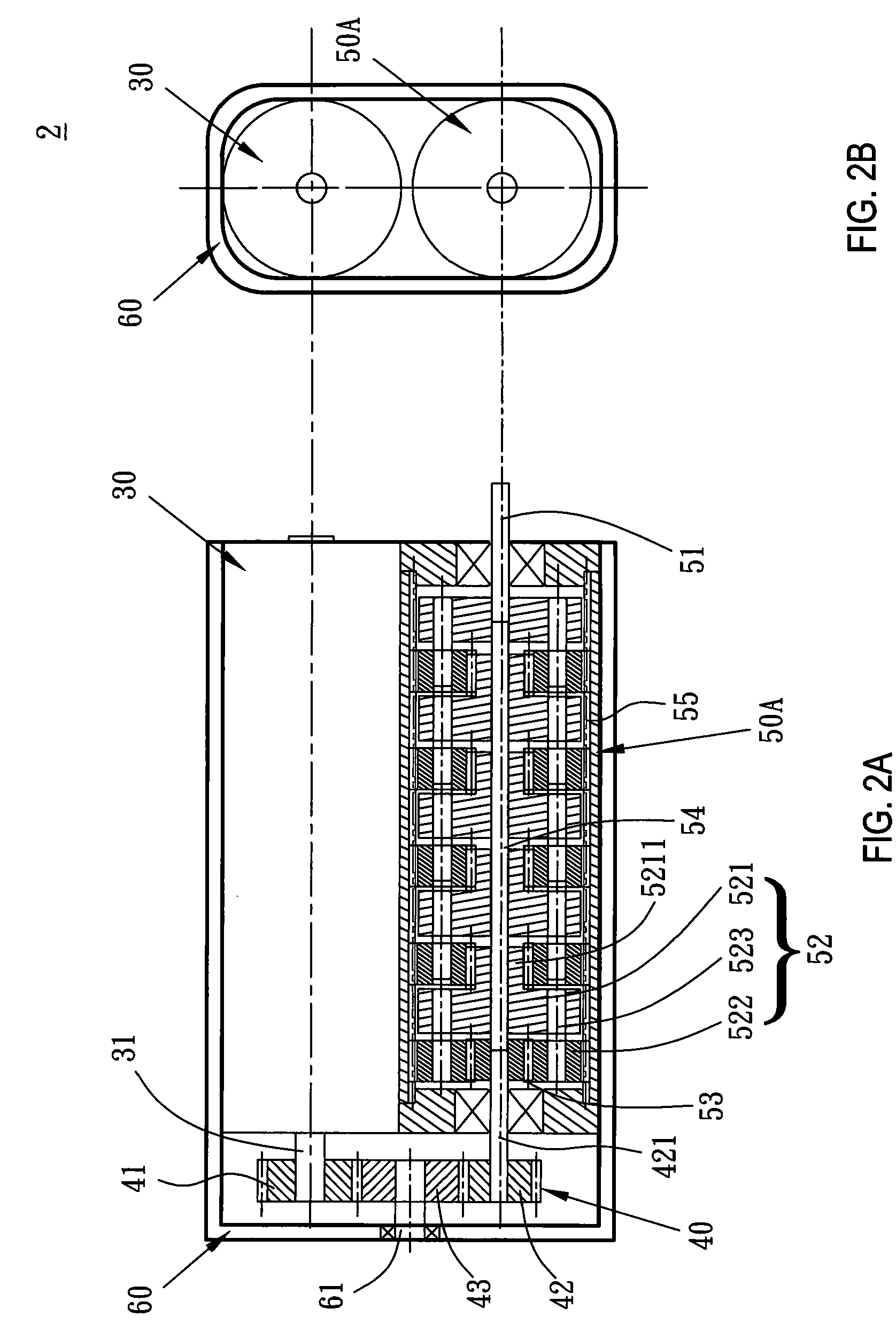
[0019]A power transmission device according to embodiments of the present invention will be described below with reference to the accompanying drawings. In the accompanying drawings, as for the secondary figure numbers A and B followed the main figure numbers, A indicates a cross-sectional view of a power transmission device, and B indicates a side view of the power transmission device.

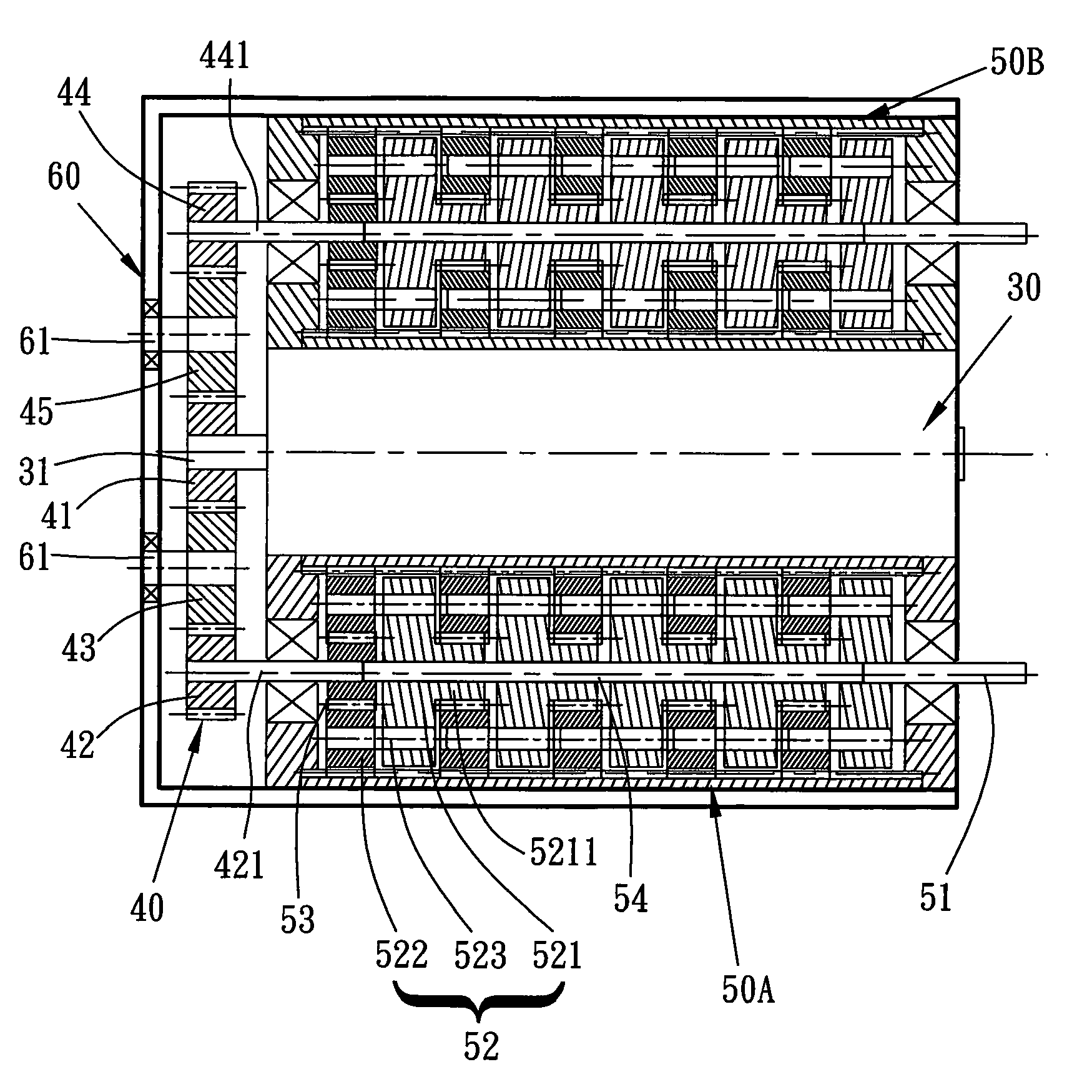
[0020]FIGS. 2A and 2B are schematic views of a first embodiment of the present invention. A power transmission device 2 in this embodiment includes a first motor 30, a first intermediate gearset 40, and a first planetary gearset assembly 50A. The first motor 30 has a first motor output shaft 31. The first intermediate gearset 40 has a first input gear 41 connected to the first motor output shaft 31. The first motor 30 drives a first intermediate gear output shaft 421 of a first output gear 42 of the first intermediate gearset 40. The first planetary gearset assembly 50A has an input end connected to t...


PUM


Abstract

A power transmission device is provided. The power transmission device includes a motor, an intermediate gearset, and a planetary gearset assembly. The motor includes a motor output shaft. The intermediate gearset has an input gear connected to the motor output shaft. The motor drives an intermediate gear output shaft of an output gear of the intermediate gearset. The planetary gearset assembly has an input end connected to the intermediate gear output shaft. The intermediate gear output shaft drives a planetary gear output shaft of an output end of the planetary gearset assembly.

Description

CROSS REFERENCE TO RELATED APPLICATION[0001]This application claims the benefit of Taiwan Patent Application No. 097139148, filed on Oct. 13, 2008, which is hereby incorporated by reference for all purposes as if fully set forth herein.BACKGROUND OF THE INVENTION[0002]1. Field of the Invention[0003]The present invention relates to a power transmission device, and more particularly to a power transmission device formed by a motor and gearsets within a limited space.[0004]2. Related Art[0005]In the prior art, a power transmission device generally uses a motor and gearsets to adjust a rotation speed and a torque. In practice, the gearsets that are often used in a conventional power transmission device are approximately classified into two types, one type is the intermediate gearset, and the other type is the planetary gearset. However, when being applied to structures such as robots, manipulators, electronic pets, remote control toys, or 3C electronic products, in order to save the spa...

Claims


Application Information

Patent Timeline
IPC IPC(8): F16H37/06
CPCF16H1/46H02K7/116F16H37/041F16H1/06
Inventor HUANG, GUANG-MIAOYAN, GUO-JHIHWANG, HSIN-TE
Owner METAL INDS RES & DEV CENT
Why Eureka
Try Eureka