Orthopedic device

a technology of orthopedic devices and hinges, applied in the field of orthopedic devices, can solve the problems of limiting the displacement relative of the hinge, the inability of the force strap and the hinge to work in harmony, and the bulky brace, so as to reduce the effect of medial compartmental or lateral compartmental osteoarthritis, reducing the effect of compartmental osteoarthritis, and minimizing rotational forces

Active Publication Date: 2010-04-15
OSSUR HF
View PDF99 Cites 23 Cited by
  • Summary
  • Abstract
  • Description
  • Claims
  • Application Information

AI Technical Summary

Benefits of technology

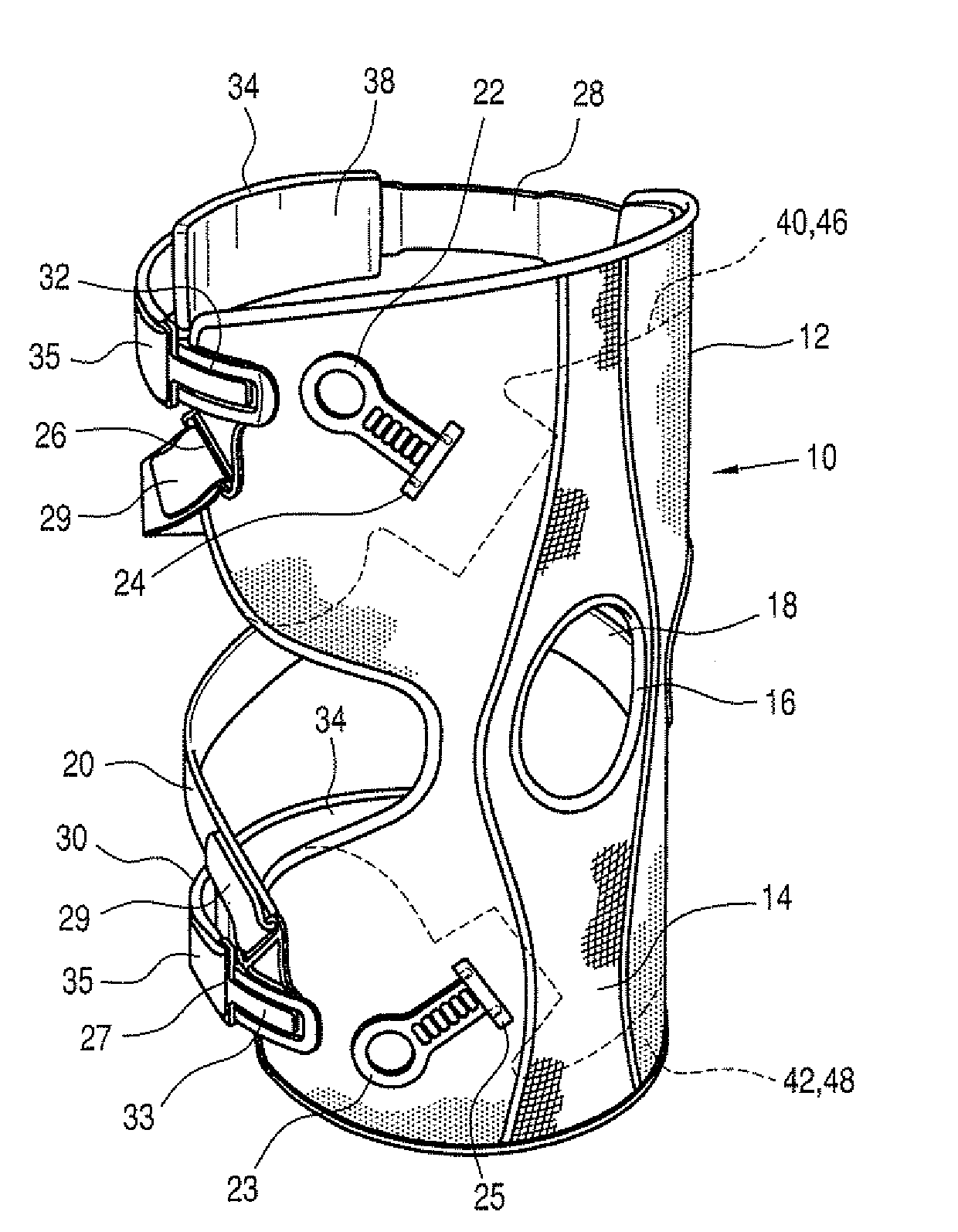
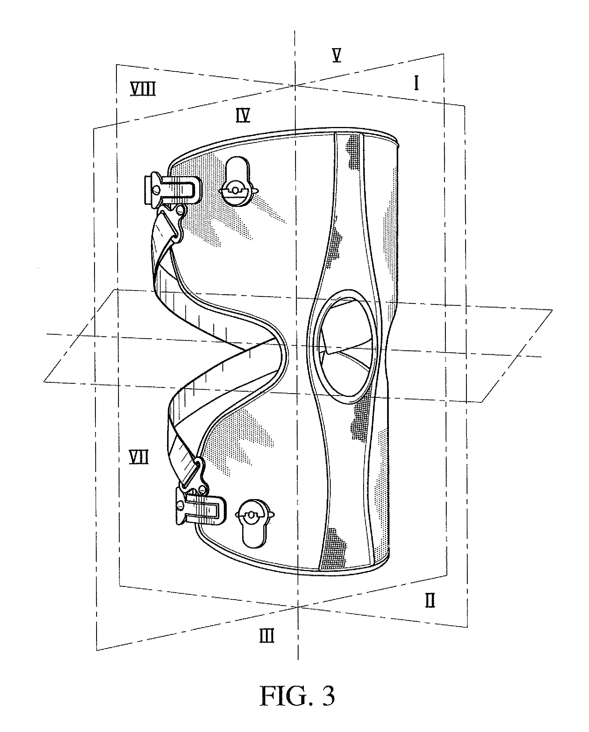
[0019]Embodiments of the present invention are described in connection to an improved knee brace and knee bracing method that serve to reduce the effects of either medial compartmental or lateral compartmental osteoarthritis. Embodiments of the knee brace and variations of the knee bracing method reduce the effects of compartmental osteoarthritis by applying multiple forces to the knee on the side remote from the compartment having osteoarthritis while providing forces on the side of the compartment to maintain the brace securely on a leg while minimizing rotational forces. The embodiments of the features described herein are not limited to usage in a knee brace, and may be extended to a variety of orthopedic and prosthetic applications.
[0023]For example, this spacer element may be used in combination with the knee brace embodiments described herein so as to prevent rotation of the knee brace on the leg of the wearer. Moreover, by providing the spacer element on both proximal and distal portions of the knee brace prevents the proximal and distal portions of the knee brace from drawing closer to one another due to the forces applied by the force straps.
[0026]In variations of the frictional layer, the frictional layer includes a plurality of apertures that correspond to apertures of the core. In an alternative variation, the frictional layer includes a plurality of apertures that are independent of apertures defined by the core. In such a variation, the frictional layer does not prevent breathability of the core.
[0028]In combination with the force straps and spacer elements of the knee brace described herein, one can achieve more unloading forces than with one force strap without increasing the pressure applied to the knee. This is due to the total unloading moment that is doubled with two force straps; the same amount of pressure is applied to the knee since there are two pressure points.
[0029]Second proximal and distal principal points of force are generated by the spacer elements secured to the frame members on a second side of the leg at locations above and below, respectively, the first proximal and distal principal points of force. The spacer elements maintain the knee brace on a leg and the frame members apart. The spacer elements may remove the need for a hinge as is used in the prior art braces.

Problems solved by technology

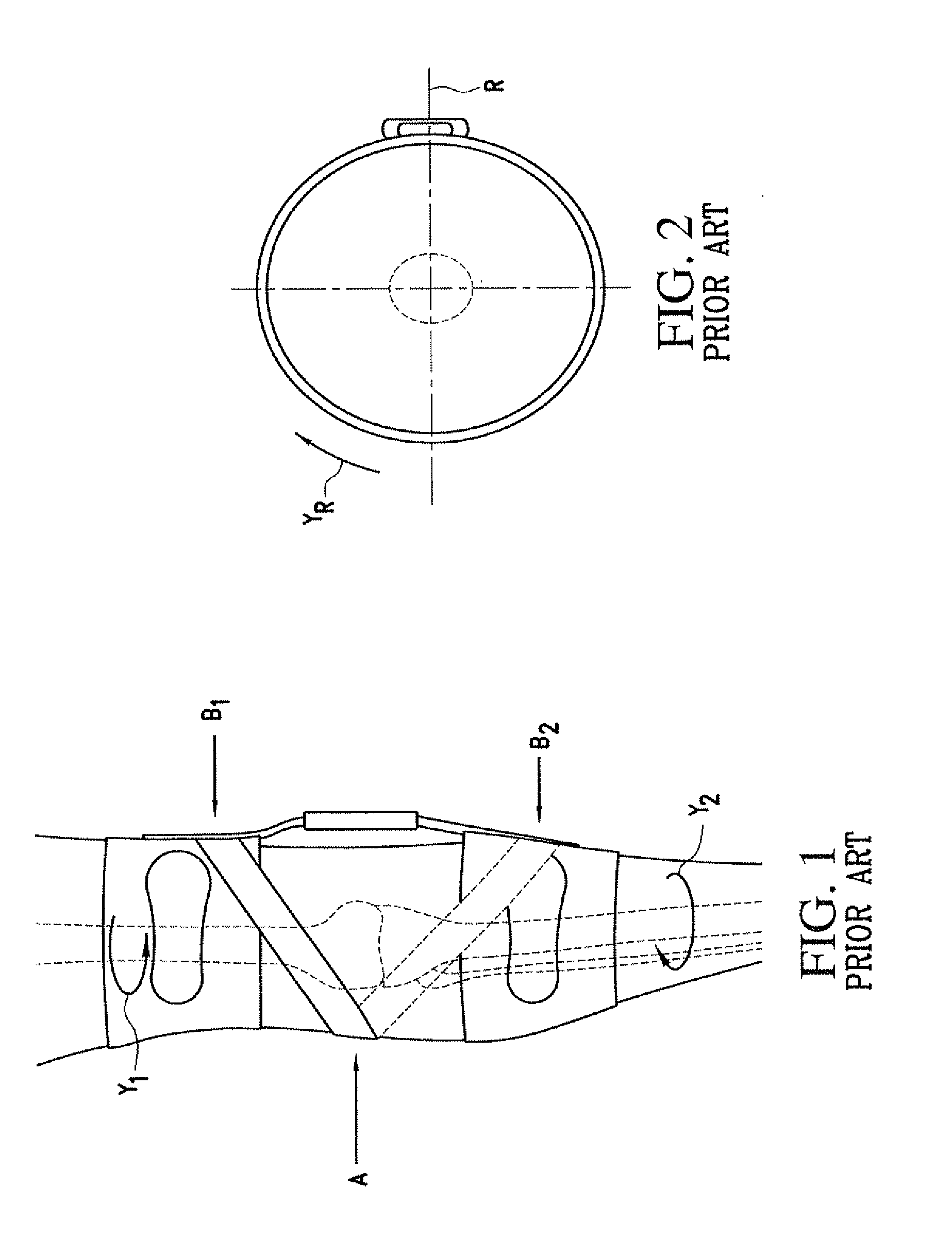
Therefore, the force strap and the hinge are found not to be adequately working in harmony.
Moreover, the rigidity of this type of hinge limits the displacement of the hinge relative to the knee.
This results in a bulky brace since a large hinge is required which may extend at least an inch away from the knee.
It has been determined that if more unloading of the knee is required by the brace than is obtained from normal strap tension, and if the force strap is further tightened, the knee is drawn towards the hinge and might strike the hinge.
This results in the hinge applying forces to the knee that counteract the force applied by the force strap.
While known knee braces are successful at reducing pain at or stabilizing a knee joint, many users find these braces to be bulky, difficult to don, complicated to configure, and uncomfortable to wear.
In such a variation, the frictional layer does not prevent breathability of the core.

Method used


Image

  • Orthopedic device
  • Orthopedic device
  • Orthopedic device

Examples


Embodiment Construction

A. Overview

[0103]A better understanding of different embodiments of the invention may be had from the following description read in conjunction with the accompanying drawings in which like reference characters refer to like elements.

[0104]While the disclosure is susceptible to various modifications and alternative constructions, certain illustrative embodiments are shown in the drawings and will be described below in detail. It should be understood, however, that there is no intention to limit the disclosure to the specific embodiments disclosed, but on the contrary, the intention is to cover all modifications, alternative constructions, combinations, and equivalents falling within the spirit and scope of the disclosure and defined by the appended claims.

[0105]It will be understood that, unless a term is expressly defined in this patent to possess a described meaning, there is no intent to limit the meaning of such term, either expressly or indirectly, beyond its plain or ordinary m...


PUM

PropertyMeasurementUnit
angleaaaaaaaaaa
forceaaaaaaaaaa
elongationaaaaaaaaaa

Abstract

A spacer element for use in an orthopedic or prosthetic device includes an apertured fabric layer having first and second fabric layers. A discrete and continuous web-like frictional layer is laminated onto the first fabric layer and has greater frictional properties than the fabric layer. The frictional layer has a plurality of apertures arranged in a pattern in direct correspondence to a pattern of the first surface layer apertures. A compressible material layer has opposed first and second surfaces, wherein the first surface is secured to the second surface layer. The compressible material layer has a first compression molded region with reduced thickness and increased density relative to a second region of the compressible material having a predetermined thickness.

Description

CROSS REFERENCE TO RELATED APPLICATIONS[0001]This application is a continuation-in-part of U.S. application Ser. No. 11 / 723,604 filed on Mar. 21, 2007, which is a continuation-in-part of U.S. application Ser. No. 11 / 312,337 filed on Dec. 21, 2005, which claims the benefit of U.S. provisional application Nos. 60 / 637,754 filed Dec. 22, 2004, 60 / 684,163 filed May 25, 2005, and 60 / 739,407 filed Nov. 25, 2005. All of these noted priority documents are incorporated herein by reference in their entirety.BACKGROUND[0002]A. Background Information on Knee Braces[0003]Knee braces are widely used to treat a variety of knee infirmities. Such braces may be configured to impart forces or leverage on the limbs surrounding the knee joint in order to relieve compressive forces within a portion of the knee joint, or to reduce the load on that portion of the knee. Moreover, in the event that knee ligaments are weak and infirm, a knee brace may stabilize, protect, support, or rehabilitate the knee.[0004...

Claims


Application Information

Patent Timeline
Patent Type & Authority Applications(United States)
IPC IPC(8): A61F5/00
CPCA61F5/0123A61F2005/0139Y10T428/24273A61F2005/0181Y10T428/24322A61F2005/0174Y10T442/2328
Inventor INGIMUNDARSON, ARNI THOREINARSSON, PALMI
Owner OSSUR HF
Why Eureka
Try Eureka