Movable Intervertebral Disc Prosthesis

a technology of intervertebral discs and prostheses, which is applied in the field of moving intervertebral disc prostheses or artificial discs, can solve the problems of unnatural prosthesis, premature wear of the prosthesis, and possible further wear of the movement segment, and achieve the effect of easy and rapid assembly

Inactive Publication Date: 2010-04-15
GLOBAL MEDICAL CONSULTING
View PDF6 Cites 10 Cited by
  • Summary
  • Abstract
  • Description
  • Claims
  • Application Information

AI Technical Summary

Benefits of technology

[0012]By means of this possibility for adjusting or post adjusting the prosthesis, the position of the pivot point can be deliberately placed or corrected, and hence extensively optimally disposed, without altering the position of the prosthesis and the positive anchoring condition. Application occurs on conventional and tested prosthesis systems.
[0013]The present invention has the advantage that the prosthesis is adjusted for optimizing the position of the pivot point, whereby the prosthesis components or modules that define the pivot point do not twist in an uncontrolled manner, as is the case with the aforementioned state of the art.
[0014]Modular prostheses are generally used, with which the prosthesis modules that define the pivot point are configured so as to be shiftable or displaceable in a translatory manner and in one or two dimensions relative to the natural end plates of the adjoining vertebra bodies. I...

Problems solved by technology

If this pivot point does not lie in the equilibrium plane of the natural movement sequence, premature wear of the prosthesis, and possibly also further wear of the movement segment, can occur.
Although the rotational cente...

Method used


Image

  • Movable Intervertebral Disc Prosthesis
  • Movable Intervertebral Disc Prosthesis
  • Movable Intervertebral Disc Prosthesis

Examples


Embodiment Construction

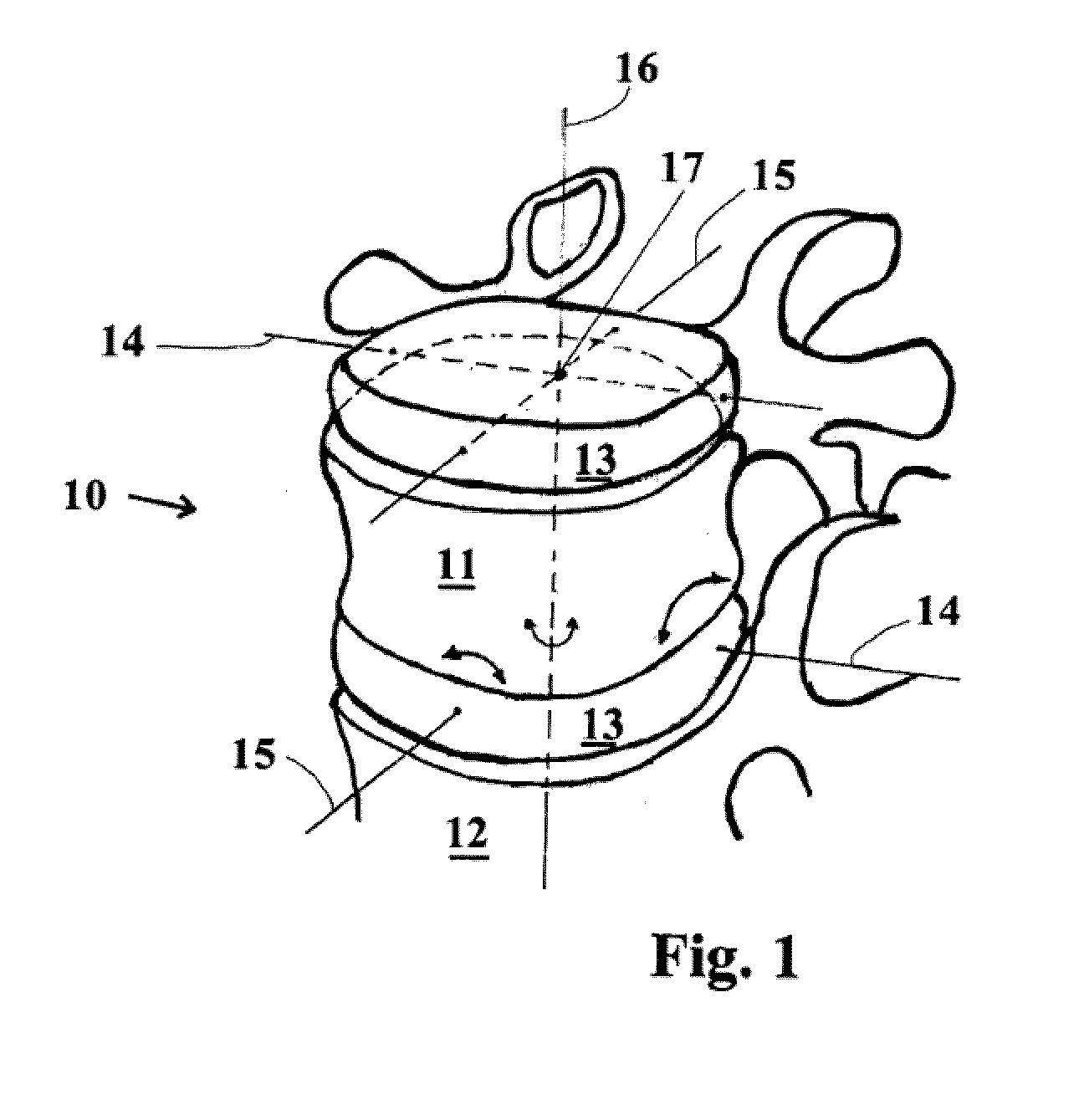
[0025]Referring now to the drawings in detail, FIG. 1 illustrates a vertebrae segment 10 composed of two vertebra bodies 11, 12 and an intervertebral disc 13. When the patient moves, the vertebra bodies 11, 12 of the vertebrae segment 10 carry out or execute relative movements about an extension / bending axis 14 and a lateral tilting axis 15 as well as pivoting or rotating about a vertical axis 16. These axes 14-16 intersect in a pivot point 17. This natural pivot point 17 ends up approximately in the rear third of the intervertebral disc.

[0026]If the natural intervertebral disc 13 is replaced by a movable implant, an artificial pivot point is reproduced to obtain the moveability of appropriately moveably configured implant components or modules.

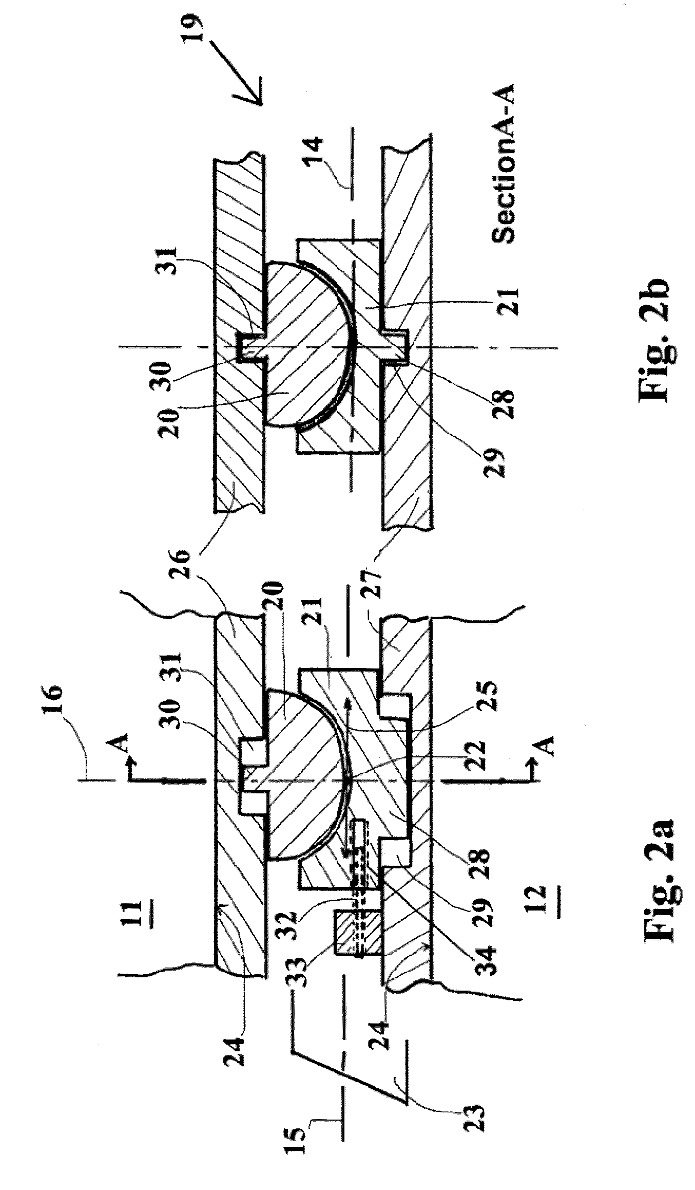
[0027]A straightforward example is a hemisphere / socket prosthesis or artificial disc, as illustrated in longitudinal section in the direction ventral-dorsal in FIG. 2a. FIG. 2b shows a longitudinal section A-A taken transverse to FIG. 2a.

[00...


PUM


Abstract

A movable intervertebral disc prosthesis having a pivot point and adapted to be implanted between vertebra bodies to form a vertebrae segment. In an implanted state three-dimensional movement axes of the vertebrae segment intersect in the pivot point. The configuration of the prosthesis is such that a deliberate displacement or shifting of the pivot point can be carried out prior to, during and/or after the implantation.

Description

[0001]The instant application should be granted the priority date of Oct. 14, 2008 the filing date of the corresponding German patent application DE 10 2008 051 588.4BACKGROUND OF THE INVENTION[0002]The present invention relates to a movable intervertebral disc prosthesis or artificial disc having a pivot point, whereby in the implanted state three-dimensional movement axes of a vertebrae segment intersect.[0003]The implantation of movable intervertebral disc prostheses requires great care, which relates to the pivot point. The natural pivot point, via which an entire vertebrae segment is moved, normally lies in the rear third of the intervertebral disc. Furthermore, the natural pivot point moves on a plane, essentially following a circle, depending upon the positions or orientations of the vertebra bodies of the patient.[0004]Conventional movable intervertebral disc prostheses define a pivot point that in the implanted state assumes a fixed position. If this pivot point does not li...

Claims


Application Information

Patent Timeline
IPC IPC(8): A61F2/44
CPCA61F2/4425A61F2002/30369A61F2002/30555A61F2250/0008A61F2002/443A61F2220/0033A61F2002/30662
Inventor BERTAGNOLI, RUDOLF
Owner GLOBAL MEDICAL CONSULTING
Why Eureka
Try Eureka