Anti-backflow valve

Inactive Publication Date: 2010-04-22
GLOBE UNION INDAL
View PDF5 Cites 19 Cited by
  • Summary
  • Abstract
  • Description
  • Claims
  • Application Information

AI Technical Summary

Benefits of technology

[0014]The present invention is directed to an anti-backflow valve having a good operatio

Problems solved by technology

1. Since the water flow has to flow through the accommodating chamber via the gap between the plug and the inner wall of the accommodating chamber, the plug has to be designed to be of a certain size smaller than the inner wall of the accommodating chamber. Moreover, since the O-ring is engaged on the plug and used to press against the end face of the accommodating chamber so as to achieve the enclosed state, the end face has to be of a certain size smaller than the plug, which causes the inlet to have a fairly small size. In this manner, the active area of the water flow on the plug through the inlet correspondingly becomes small, which will cause the motion of the plug to become insensitive and thus cause a problem of water flux control.
2. The check valve is pressed against the end face of the accommodating chamber by the O-ring of the plug so as to block the water flow. In order to achieve the effect of blocking the water flow

Method used


Image

  • Anti-backflow valve
  • Anti-backflow valve
  • Anti-backflow valve

Examples


Embodiment Construction

[0029]As for the technical means adopted in the present invention to achieve the above objective, a detailed illustration is given below through the embodiment and accompanying drawings.

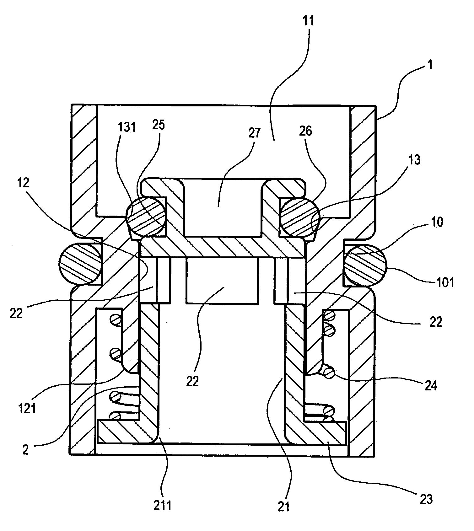
[0030]FIG. 4 is a three-dimensional exploded view of the present invention, and FIG. 5 is a combined cross-sectional view of the present invention. An anti-backflow valve of the present invention is suitable for being assembled into a pipe of a water-supply facility, for example, into a pipe within a faucet or a pipe within a shower assembly.

[0031]An anti-backflow valve of the present invention includes a valve seat 1 and a plug 2 slidingly disposed in the valve seat 1. An outer edge of the valve seat 1 has an annular groove 10 recessed therein, and the annular groove 10 has a sealing ring 101 disposed therein. The valve seat 1 has a flow passage 11 penetrating therethrough. A middle section of the flow passage 11 has a ring portion 12 protruding inwards. The ring portion 12 has a seat portion 13 ext...


PUM


Abstract

An anti-backflow valve, including a valve seat and a plug slidingly disposed in the valve seat, is provided. The valve seat has a ring portion protruding inwards at a middle section of a flow passage thereof. The ring portion has a seat portion extended outwards on one side thereof. The plug has an accommodating chamber recessed inwards on one side thereof. The accommodating chamber has an opening radially penetrating through the plug at one end thereof distant from an inlet. The plug has a protruding portion at one end thereof adjacent to the inlet. An outer diameter of the protruding portion is larger than an inner diameter of the ring portion. A spring is provided between the protruding portion and the ring portion, and a portion of the plug penetrating through the ring portion has an O-ring engaged thereon corresponding to the seat portion.

Description

BACKGROUND OF THE INVENTION[0001]1. Field of Invention[0002]The present invention relates to a technical field of anti-backflow valves for water-supply facilities, and more particularly to an anti-backflow valve structure having a good operational sensitivity and a high degree of design freedom.[0003]2. Related Art[0004]Generally, in order to maintain pressure equilibrium between cold and hot water supply flow passages within a faucet and prevent a back flow, a check valve is additionally provided in the flow passages, for ensuring a smooth water outflow. In addition, in flow passages of a pull-out faucet, in order to prevent a back siphonage, a check valve is additionally provided in the flow passages as well.[0005]FIG. 1 is a schematic view of a conventional check valve being assembled on a faucet pipe. Referring to FIG. 1, a cold water inlet 81 and a hot water inlet 82 of a faucet 8 are respectively provided with one check valve 9, so as to prevent a back flow.[0006]FIG. 2 is a s...

Claims


Application Information

Patent Timeline
IPC IPC(8): F16K15/02
CPCF16K15/026Y10T137/7925
Inventor QIU, WEI-DONG
Owner GLOBE UNION INDAL
Why Eureka
Try Eureka