Rear door heat exchanger transition frame

a heat exchanger and transition frame technology, applied in the direction of heat transfer modification, electrical equipment, lighting and heating apparatus, etc., can solve the problems of over-crowding of servers, over-crowding of cooling components, and exceeding the needs and budget of start-ups and cost-sensitive operations

Inactive Publication Date: 2010-04-22
VETTE TECH
View PDF8 Cites 26 Cited by
  • Summary
  • Abstract
  • Description
  • Claims
  • Application Information

AI Technical Summary

Benefits of technology

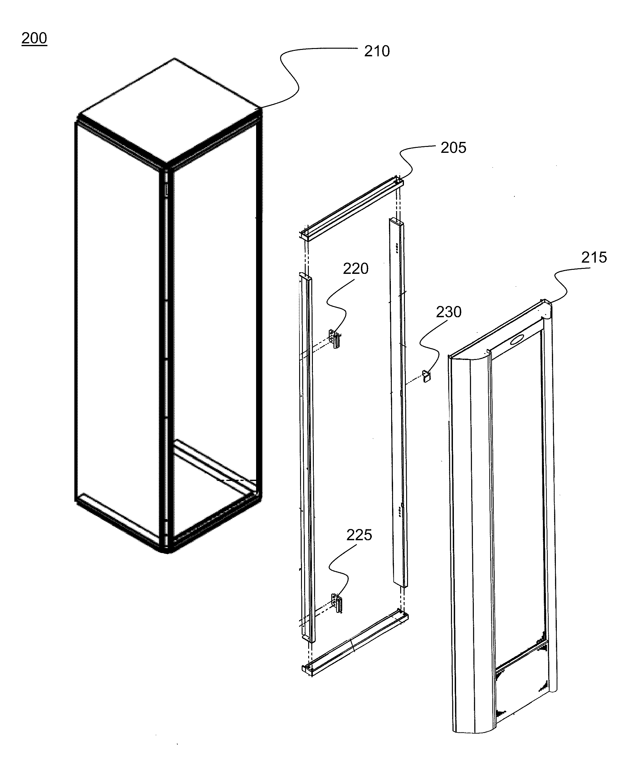
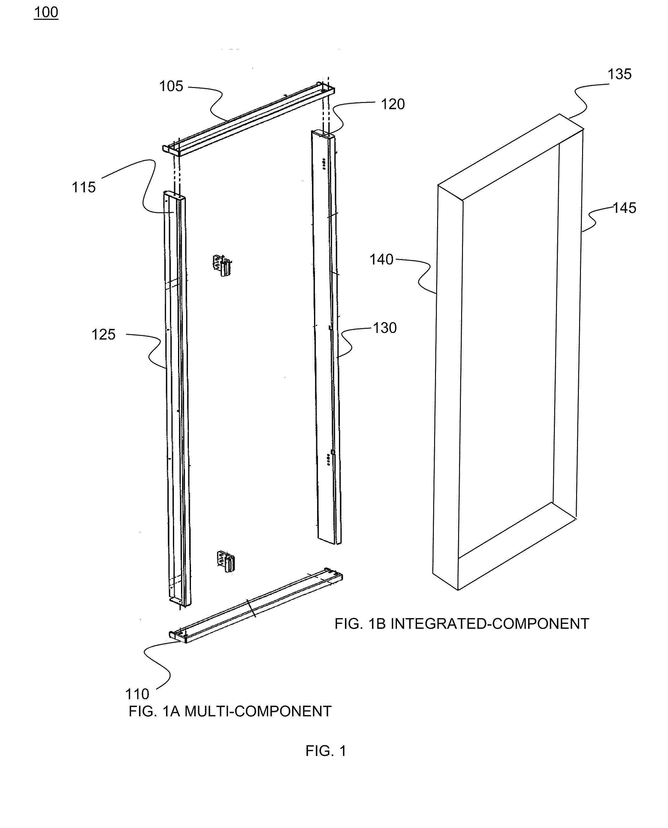
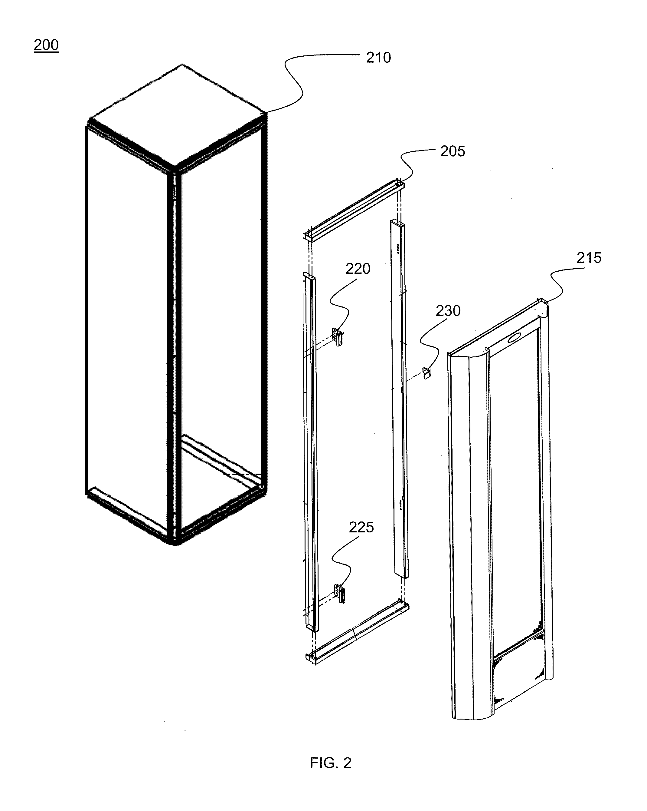
[0009]A system and method for integrating a liquid cooling door with associated computer equipment racks is disclosed. Transition frame embodiments include replacements for rack hinges and latches, overcoming the lack of standards in this area. The solution enables the purchase of inexpensive air-cooled racks initially, when relatively few components are installed. Then, as rack capacity is reached by adding components resulting in peak heat loads, the existing rack can be retrofitted with a rear door heat exchanger.

Problems solved by technology

This has reached the point where air conditioning systems are unable to cool computing facilities without supplemental liquid cooling.
For example, temperatures can climb 2 degrees Centigrade per minute following air conditioning failure, resulting in server shut down and 100 degree Fahrenheit temperatures in less than 15 minutes.
These are expensive and often exceed the needs and budget of start-ups and cost-sensitive operations.
Currently, the upgrade options available are limited and operationally prohibitive, often requiring shutting down equipment and replacing the racks housing it.
This rack replacement involving shutting down mission critical servers, removing the hardware, and reinstalling the equipment is a very expensive and labor intensive process.
No alternative may exist though, if expansion requires a new rack to accommodate a rear door heat exchanger.
While standardized rack sizes exist, variations prevent direct interchangeability of components such as doors.
This lack of interchangeability requires an extensive initial investment for a more advanced rack than may be required at start-up if rear door heat exchangers are anticipated.

Method used


Image

  • Rear door heat exchanger transition frame
  • Rear door heat exchanger transition frame
  • Rear door heat exchanger transition frame

Examples


embodiment 300

[0040]FIG. 3 is a diagram of components comprising a first transition frame embodiment 300 depicting vertical side 305 and cross section A-A 310 of vertical side 305. Second view 315 of vertical side depicts view B-B of section 310. Perspective view of horizontal side 320 is also shown in orthogonal view C-C 325.

embodiment 400

[0041]FIG. 4 is a diagram of components comprising a second transition frame embodiment 400 depicting vertical side 405 and cross section A-A 410 of vertical side 405. Second view 415 of vertical side depicts view B-B of section 410. Perspective view of horizontal side 420 is also shown in orthogonal view C-C 425.

embodiment 500

[0042]FIG. 5 is a diagram of components comprising a third transition frame embodiment 500 depicting vertical side 505 and cross section A-A 510 of vertical side 505. Second view 515 of vertical side depicts view B-B of section 510. Perspective view of horizontal side 520 is also shown in orthogonal view C-C 525.


PUM


Abstract

A transition frame system integrates a liquid cooling door with associated computer equipment racks. Dissimilar dimensions of equipment racks and cooling doors are accommodated by a transition frame. The frame has a top, bottom, first side, and a second side; each providing a rack face opposing a door face. The frame may be one piece. The rack face includes a means for mating/sealing with the rack and the door face includes a means for mating/sealing with a cooling door that may include replacement hinges and latches. The transition frame can be included as part of the rack or the door. Cooling of equipment in the rack is maintained through airflow through the cooling door.

Description

RELATED APPLICATIONS[0001]This application claims the benefit of U.S. Provisional Application No. 61 / 106,691, filed Oct. 20, 2008; this application is herein incorporated in its entirety by reference.FIELD OF THE INVENTION[0002]The invention relates to a system and method to support cooling heat generating components, and more particularly, to a system and method for integrating a liquid cooling door with associated computer equipment racks.BACKGROUND OF THE INVENTION[0003]Liquid cooling of electronics cabinets to control heat rise is known. Increases in electronics density are accompanied by increases in heat production for a given volume of electronic equipment. This has reached the point where air conditioning systems are unable to cool computing facilities without supplemental liquid cooling.[0004]Competition among computing providers such as server farms, communications vendors, and data storage centers has generated a need for reliable, scalable cooling solutions as they expan...

Claims


Application Information

Patent Timeline
Patent Type & Authority Applications(United States)
IPC IPC(8): F28F13/00
CPCH05K7/20736
Inventor NOVOTNY, SHLOMOMENOCHE, JOHN P
Owner VETTE TECH
Why Eureka
Try Eureka