
Inflatable Structure for Packaging and Associated Apparatus and Method

a technology of inflatable structures and packaging, which is applied in the direction of functional valve types, packaging goods types, paper/cardboard articles, etc., can solve the problems of expensive inflation devices, difficult to achieve, and add to the complexity and cost of such inflation devices

Inactive Publication Date: 2010-04-22
SEALED AIR U S
View PDF38 Cites 35 Cited by
  • Summary
  • Abstract
  • Description
  • Claims
  • Application Information

AI Technical Summary

Benefits of technology

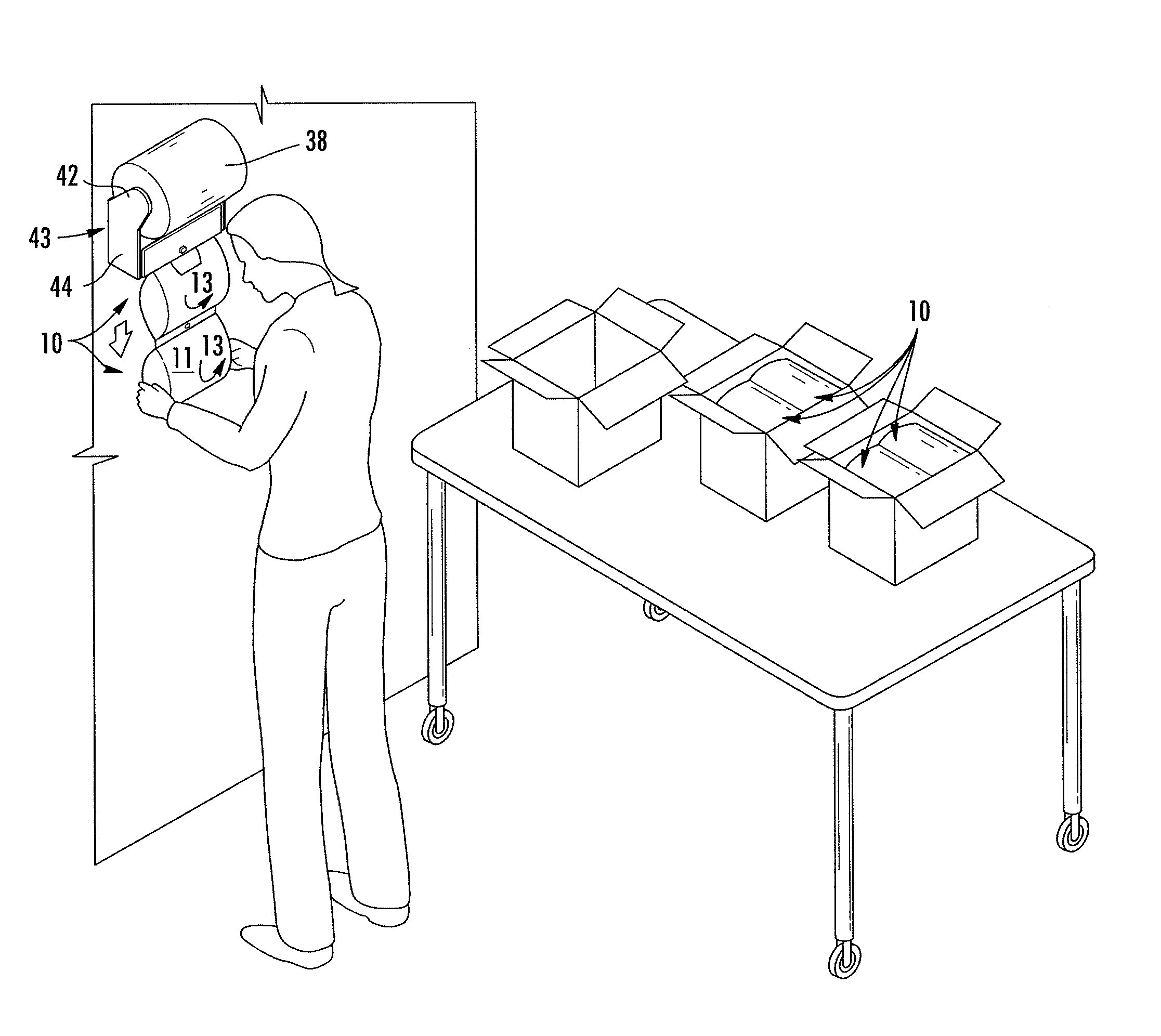
[0008]These and other advantages are provided by the inflatable structures presented herein, and which include an integral valve with two edge portions that may be formed from a single web of flexible film in an inline process. Such an inflatable structure and the associated apparatus and methods are capable of providing inflate-on-demand packaging that can be inflated using an inexpensive inflation device, and wherein such inflation is easy to do and does not require the use of an inflation needle, wand, or nozzle, or heat sealing by the entity using the packaging.
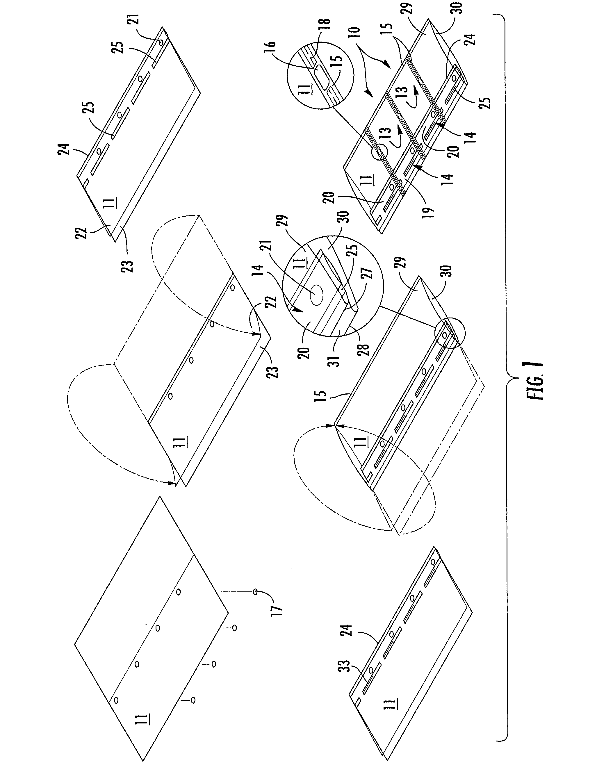
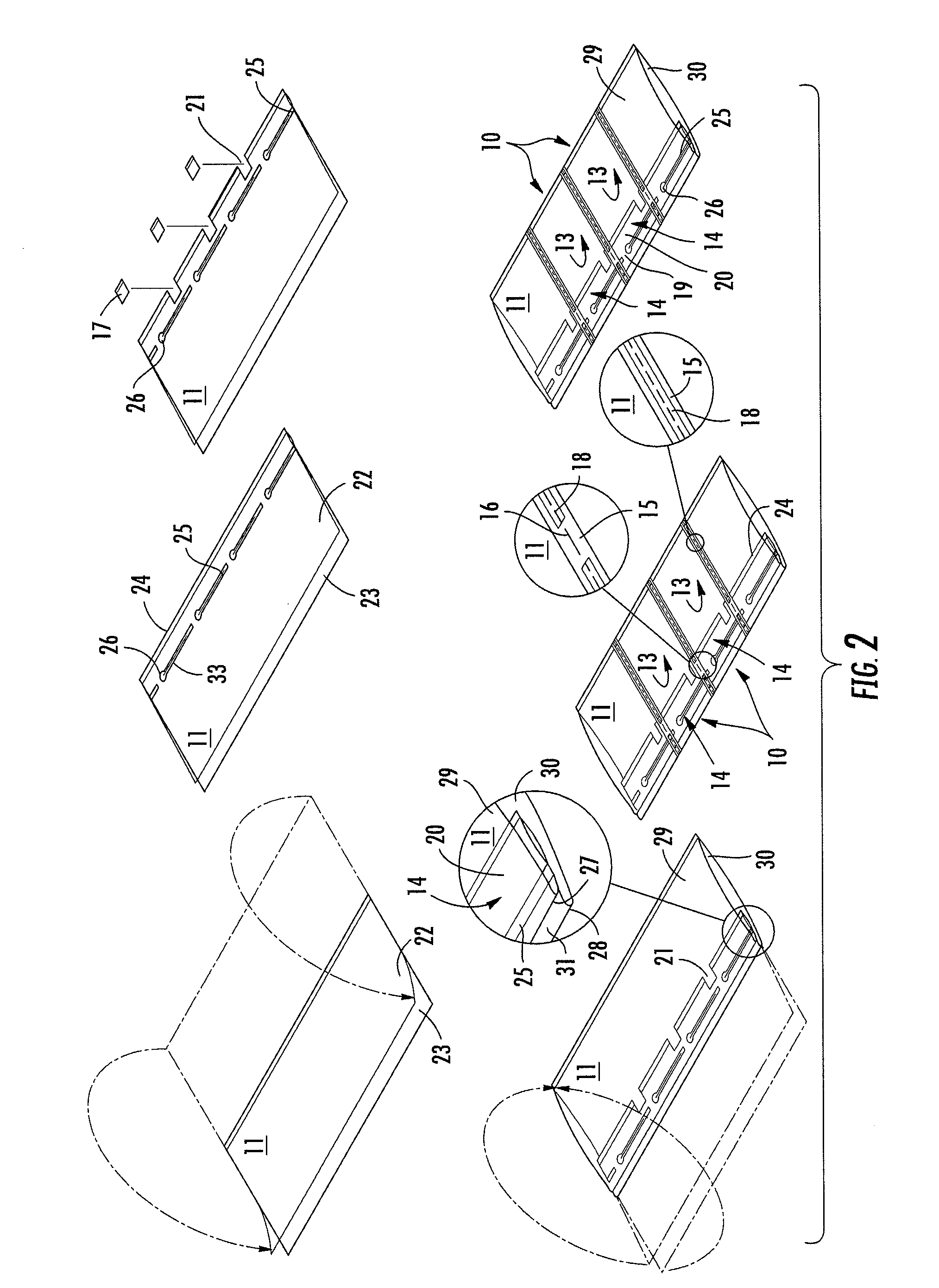
[0013]Further, a slit may be formed along at least a portion of the seals defining the valve, which, as previously described, helps the valve to maintain a seal during movement of the inflatable structure. Additionally, another step may include perforating the flexible film proximate to the perimeter seals defining the enclosed chamber to allow for separation of the inflatable structures. Also, locator apertures may be formed in the flexible film proximate to the perimeter seals defining the enclosed chamber so as to assist in locating the valve near an outlet of a source of pressurized air during inflation. With regard to the rounded portions of the seals between the first and second layers of the flexible film, these may be created by spot sealing the first layer and the second layer of the flexible film together proximate to one or more ends of the seals defining the valve. Creation of the edge portions can occur through folding the first layer of the flexible film and folding the second layer of the flexible film and offsetting the first edge portion and the second edge portion in a planar direction defined by the inflatable structure. Additional steps can include cutting the web of flexible film proximate to the perimeter seals to create multiple inflatable structures, and connecting the second edge portions of the multiple inflatable structures to thereby form a cartridge of inflatable structures. Another step could include forming an aperture in the flexible film proximate to the internal edge portion to create the internal valve opening.

Problems solved by technology

This is because prior designs typically require the use of costly inflation devices that may be hard for the entity using the packaging materials to operate.
In particular, many inflation devices rely upon heat sealing which adds to the complexity and cost of such inflation devices.
Further, many inflation devices also necessitate the insertion of an inflation wand into the valve of an inflatable structure, which can be difficult to accomplish, or they may also require careful machine-feeding of the uninflated packaging materials.

Method used


Image

  • Inflatable Structure for Packaging and Associated Apparatus and Method
  • Inflatable Structure for Packaging and Associated Apparatus and Method
  • Inflatable Structure for Packaging and Associated Apparatus and Method

Examples


Embodiment Construction

[0033]The present invention now will be described more fully hereinafter with reference to the accompanying drawings, in which some, but not all embodiments of the inventions are shown. Indeed, these inventions may be embodied in many different forms and should not be construed as limited to the embodiments set forth herein; rather, these embodiments are provided so that this disclosure will satisfy applicable legal requirements. Like numbers refer to like elements throughout.

[0034]With reference to FIG. 1, there is provided an inflatable structure 10. In this embodiment, a single piece of flexible film 11 has been formed into multiple inflatable structures 10. The inflatable structures 10 may be formed advantageously from a unitary piece of flexible film 11 in an inline process or they may be formed from multiple pieces of flexible film. Methods of manufacturing the inflatable structures 10 will be discussed below.

[0035]As used herein, the term “flexible film” refers to a material ...


PUM

PropertyMeasurementUnit
thicknessesaaaaaaaaaa
flexibleaaaaaaaaaa

Abstract

An inflatable structure generally includes a valve formed between a pair of edge portions and an internal edge portion formed of a flexible film such that an enclosed chamber of the inflatable structure substantially envelops the internal edge portion. The valve and remainder of the inflatable structure can be formed from a single piece of flexible film using a method of manufacturing an inflatable structure from a continuous web of flexible film. A corresponding inflation device fills the inflatable structure with air and may do so without requiring heat sealing or contact between the inflatable structure and outlet of the inflation device. The inflation device may include a mechanical registration device which can engage an optional locator aperture in the inflatable structure such as to assist in temporarily locating the outlet of the source of pressurized air proximate to the valve in the inflatable structure.

Description

BACKGROUND OF THE INVENTION[0001]1. Field of the Invention[0002]The present invention generally relates to inflatable structures, and in particular to inflatable structures used in packaging and associated methods and apparatus.[0003]2. Description of Related Art[0004]Inflatable structures constitute an important part of the packaging industry. Inflatable structures are commonly used as cushions to package items, either by wrapping the items in the inflatable structures and placing the wrapped items in a shipping carton, or by simply placing one or more inflatable structures inside of a shipping carton along with an item to be shipped. The cushions protect the packaged item by absorbing impacts that might otherwise be fully transmitted to the packaged item during transit, and also restrict movement of the packaged item within the carton to further reduce the likelihood of damage to the item.[0005]Inflatable packaging has an advantage over non-inflatable packaging in that inflatable ...

Claims


Application Information

Patent Timeline
Patent Type & Authority Applications(United States)
IPC IPC(8): B65D81/05F16K15/20B65B43/04B65B3/04
CPCB31D5/0073B31D2205/007F16K15/20B65D81/052B65D31/147Y10T137/3584
Inventor FRAYNE, SHAWN MICHAELCHUDY, PAUL
Owner SEALED AIR U S
Learn More