Aircraft flight control actuation system with direct acting, force limiting, actuator

a technology of flight control and actuator, applied in the field of actuation systems, can solve the problems of stalling input, worm shaft rub on relatively displaced worm gear, etc., and achieve the effect of amplifying reaction forces

Active Publication Date: 2010-04-22
PARKER INTANGIBLES LLC
View PDF12 Cites 27 Cited by
  • Summary
  • Abstract
  • Description
  • Claims
  • Application Information

AI Technical Summary

Benefits of technology

[0007]The present invention provides a direct acting force limiting actuator wherein the actuator output force either directly or indirectly causes significant drag on a rotary input shaft rather than on the translating output member. Consequently, input energy is dissipated before the actuator gear train mechanical advantage amplifies the reaction forces.

Problems solved by technology

When the load on the output member becomes excessive and exceeds the pre-specified value, the load causes the worm gear to translate relative to the worm shaft and cause the worm shaft to rub on the relatively displaced worm gear.
This creates a friction drag on the worm shaft that can ultimately lock the input from imparting any further load on the output member.
Movement of the brake actuator member causes a brake coupled to the input to be engaged and thereby apply a braking force to the input shaft and eventually stall the input.

Method used


Image

  • Aircraft flight control actuation system with direct acting, force limiting, actuator
  • Aircraft flight control actuation system with direct acting, force limiting, actuator
  • Aircraft flight control actuation system with direct acting, force limiting, actuator

Examples


Embodiment Construction

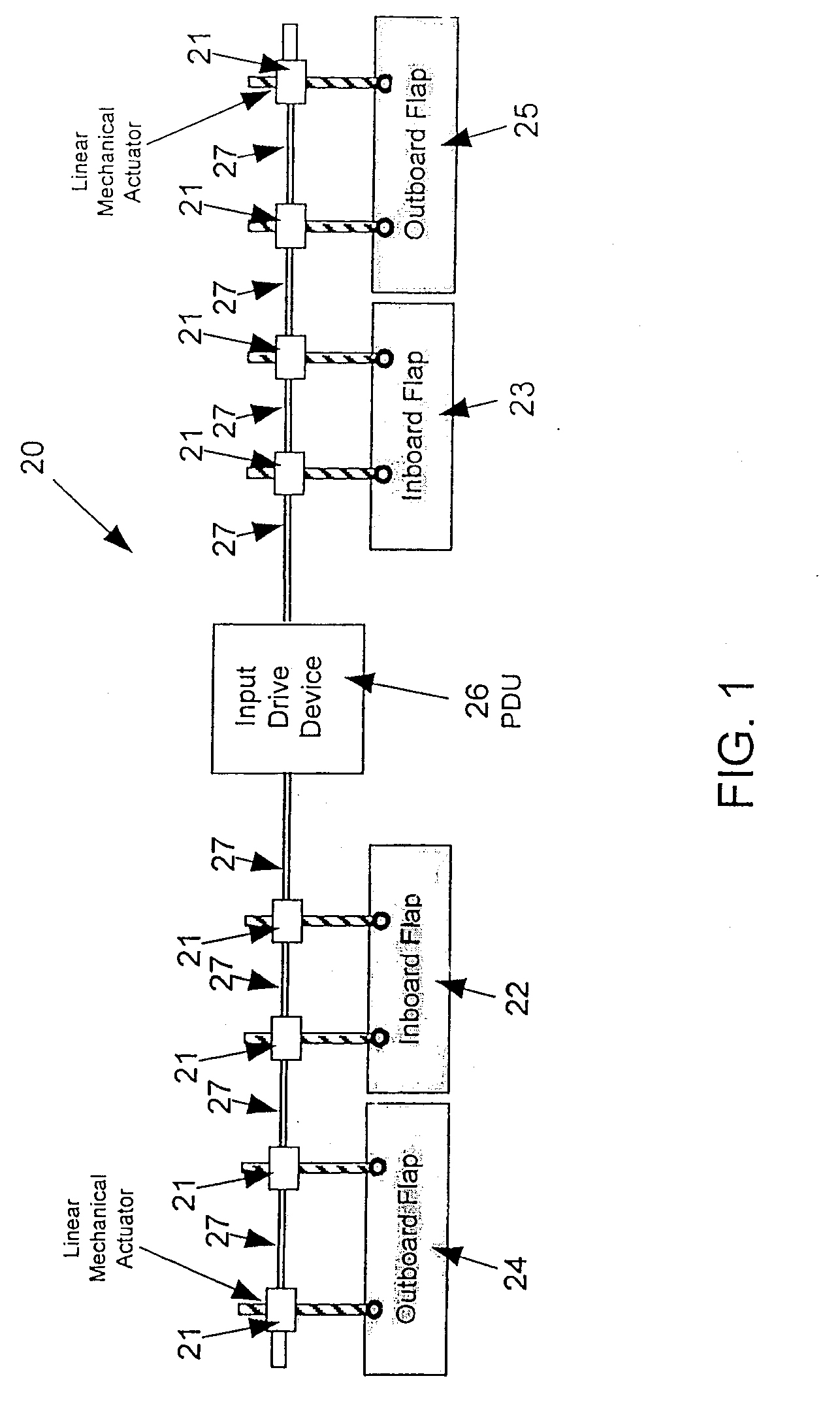
[0032]Referring now in detail to the drawings and initially to FIG. 1, an exemplary flap system 20 can be seen to comprise eight flap actuators 21 for driving four flap panels 22-25. As will be appreciated, the number of flap panels and actuators may be varied for a given application, but usually there will be one or more flap panels on each wing and a like number on the other wing. Each flap panel may be driven by one or more actuators 21. In the illustrated embodiment, the inboard flap panels 22 and 23 and outboard panels 24 and 25 are all driven by two actuators each. It will also be appreciated that the principles of the invention may be applied to any system where linear mechanical actuators are used and load limiting is required, and the use herein of the term control surface panel is intended to encompass any type of controlled item including but not limited to; flaps, slats, doors, stabilizers and other similar devices. The following description, however, will refer to flap ...


PUM


Abstract

A direct acting force limiting actuator wherein the actuator output force either directly or indirectly causes significant drag on a rotary input shaft rather than on the translating output member. Consequently, input energy is dissipated before the actuator gear train mechanical advantage amplifies the reaction forces.

Description

RELATED APPLICATION[0001]This application claims the benefit of U.S. Provisional Application No. 60 / 890,203 filed Feb. 16, 2007, which is hereby incorporated by reference in its entirety.FIELD OF THE INVENTION[0002]The present invention relates to actuation systems, and more particularly to aircraft flight control actuation systems.BACKGROUND[0003]Modern aircraft wings often include a series of movable flight control surfaces, known as flaps or slats, that can be selectively extended or retracted to modify the lift producing characteristics of the wings. Extension and retraction of such flaps or slats is accomplished by a flight control actuation system mounted in the wing.[0004]A typical actuation system includes a series of actuators spaced along the span of each wing, and operably connected to move one or more individual flight control surfaces. Adjacent actuators are connected to each other by drive shafts to form a chain of actuators and shafts extending along the span of the w...

Claims


Application Information

Patent Timeline
Patent Type & Authority Applications(United States)
IPC IPC(8): B64C13/28F16H25/20F16H25/22
CPCB64C13/28B64D45/0005B64D2045/001F16H25/2021F16H2025/209Y10T74/18576Y10T74/19749Y10T74/19702Y10T74/18696Y10T74/18704Y02T50/44Y02T50/40
Inventor MCKAY, TED ALEXANDER
Owner PARKER INTANGIBLES LLC
Why Eureka
Try Eureka