Microelectromechanical system microphone package

a micro-electromechanical and microphone technology, applied in the field of integrated circuit (ic) packages, can solve the problems of high cost of electrically conductive materials and short circuit of electronic components on the substrate, and achieve the effect of effective enhancement of packaging yield and lowering the cost of its produ

Inactive Publication Date: 2010-04-22
LINGSEN PRECISION INDS
View PDF2 Cites 11 Cited by
  • Summary
  • Abstract
  • Description
  • Claims
  • Application Information

AI Technical Summary

Benefits of technology

[0007]The primary objective of the present invention is to provide an MEMS microphone package, which can effectively enhance the packaging yield and lower the cost for its product.
[0008]The foregoing objective of the present invention is attained by the MEMS microphone package composed of a substrate, a cover, a plurality of conductive members, and an insulative adhesive. The cover is mounted to the substrate. The conductive members are disposed between the substrate and the cover. Each of the conductive members can be a golden wire, a conductive bump, or a conductive metal, having a upper end and a lower end. The upper ends of the conductive members are connected with the cover and the lower ends of the conductive members are connected with the substrate to enable a conductive loop. The insulative adhesive encapsulates the conductive members. In this way, the substrate, the conductive members, and the cover jointly construct a shielding against electromagnetic interference (EMI).

Problems solved by technology

However, the conductive adhesive or the solder tends to be coated excessively, during sealing the opening, to overflow into the substrate within the cover, thus causing short circuit of electronic components on the substrate.
Besides, such electrically conductive material is high-cost because of its complicated production process.

Method used


Image

  • Microelectromechanical system microphone package
  • Microelectromechanical system microphone package
  • Microelectromechanical system microphone package

Examples


Embodiment Construction

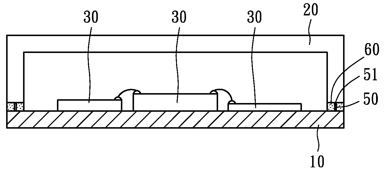
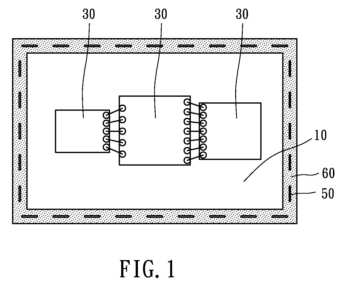
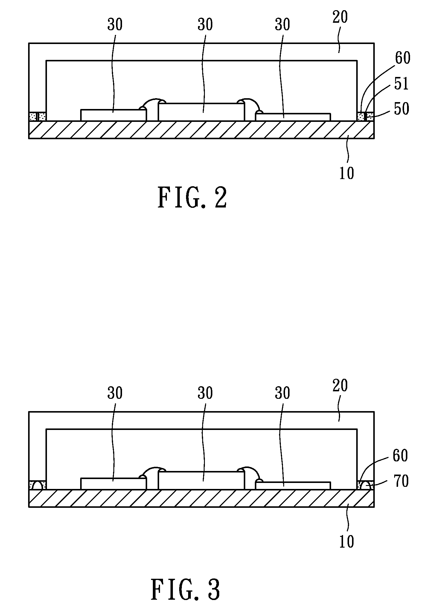
[0012]Referring to FIGS. 1 and 2, an MEMS microphone constructed according to a first preferred embodiment of the present invention is composed of a substrate 10, a cover 20 mounted to the substrate 10, and a plurality of electronic components 30, like sensor chips or passive components, located on the substrate 10. A conductive material layer is disposed at a peripheral edge of the substrate 10. Another conductive material layer is disposed on a surface of the cover 20. Because the present invention is focused on the package of the substrate 10 and the cover 20, the relevant operation of the electronic components 30 will not be recited thereafter.

[0013]During the IC packaging of the present invention, a plurality of golden wires 50, each of which has an arc tip having the same height, are firstly mounted to where the substrate 10 and the cover 20 contact each other by wire bonding, surrounding the periphery of the substrate 10. Next, an insulative adhesive 60 fully encapsulates the...


PUM


Abstract

An MEMS microphone package includes a substrate, a cover, a plurality of conductive members, and an insulative adhesive. The cover is mounted to the substrate. The conductive members are disposed between the substrate and the cover. Each of the conductive members can be a golden wire, a conductive bump, or a conductive metal. Upper ends of the conductive members are connected with the cover and the lower ends of the conductive members are connected with the substrate to enable a conductive loop. The insulative adhesive encapsulates the conductive members. In this way, the substrate, the conductive members, and the cover jointly construct a shielding against EMI.

Description

BACKGROUND OF THE INVENTION[0001]1. Field of the Invention[0002]The present invention relates generally to integrated circuit (IC) packages, and more particularly, to a microelectromechanical system (MEMS) microphone package.[0003]2. Description of the Related Art[0004]As the technology develops quickly, a variety of new and innovative products keep presented. To satisfy the consumers' requirement for convenient operation and portability, the electronic products are researched and developed to be lightweight, thin, short, and small. Among those electronic products, the MEMS microphone is very popular.[0005]A typical MEMS microphone was disclosed by U.S. Pat. No. 6,781,231 filed by Knowles Electronics and entitled “MEMS SYSTEM PACKAGE WITH ENVIRONMENTAL AND INTERFERENCE SHIELD”, which is composed of an MEMS system microphone, a substrate, and a cover. An end edge of an opening of the cover is electrically connected with the substrate by an electrically conductive material, like condu...

Claims


Application Information

Patent Timeline
Patent Type & Authority Applications(United States)
IPC IPC(8): H01L29/84
CPCH01L23/10H01L23/552H01L2924/1461H01L2924/3025H01L2924/165H01L25/0655H01L25/16H04R19/005H04R19/04H01L2224/48195H01L2924/16251H01L2924/00
Inventor TIAN, JYONG-YUE
Owner LINGSEN PRECISION INDS
Why Eureka
Try Eureka