
Display device and display method

a display device and display method technology, applied in the field of display devices, can solve the problems of loss of information of the decimated portion of the original pixel data, loss of a high-frequency component of the 1-frame image, so as to prevent the loss of the high-frequency component

Inactive Publication Date: 2010-04-22
FUJITSU GENERAL LTD
View PDF7 Cites 94 Cited by
  • Summary
  • Abstract
  • Description
  • Claims
  • Application Information

AI Technical Summary

Benefits of technology

[0017]As has been described hereinbefore, the present invention has made it possible to provide a cheap display device and a display method that are capable of preventing loss of high-frequency component during generation of a video signal from a source signal while at the same time securing continuity of pixel data.

Problems solved by technology

In such cases, mounting two displays requires a large mounting space, and further, increases the cost.
However, when, during generation of the video signal, the original pixel data constituting the video source signal is subjected only to decimation processing in a predetermined direction, the information of the decimated portion of the original pixel data might be lost, resulting in not only loss of a high-frequency component of the 1-frame image but also a lack of continuity between adjacent pieces of pixel data.
Thus, such a problem results that the video shown on the display on the basis of such video signal is extremely hard to see.

Method used


Image

  • Display device and display method
  • Display device and display method
  • Display device and display method

Examples


Embodiment Construction

[0036]The following describes basic embodiments of the display device according to the present invention by referring to the drawings. It should be noted that the present invention will not be limited in technical scope by the following embodiments but by the appended claims and equivalents thereof.

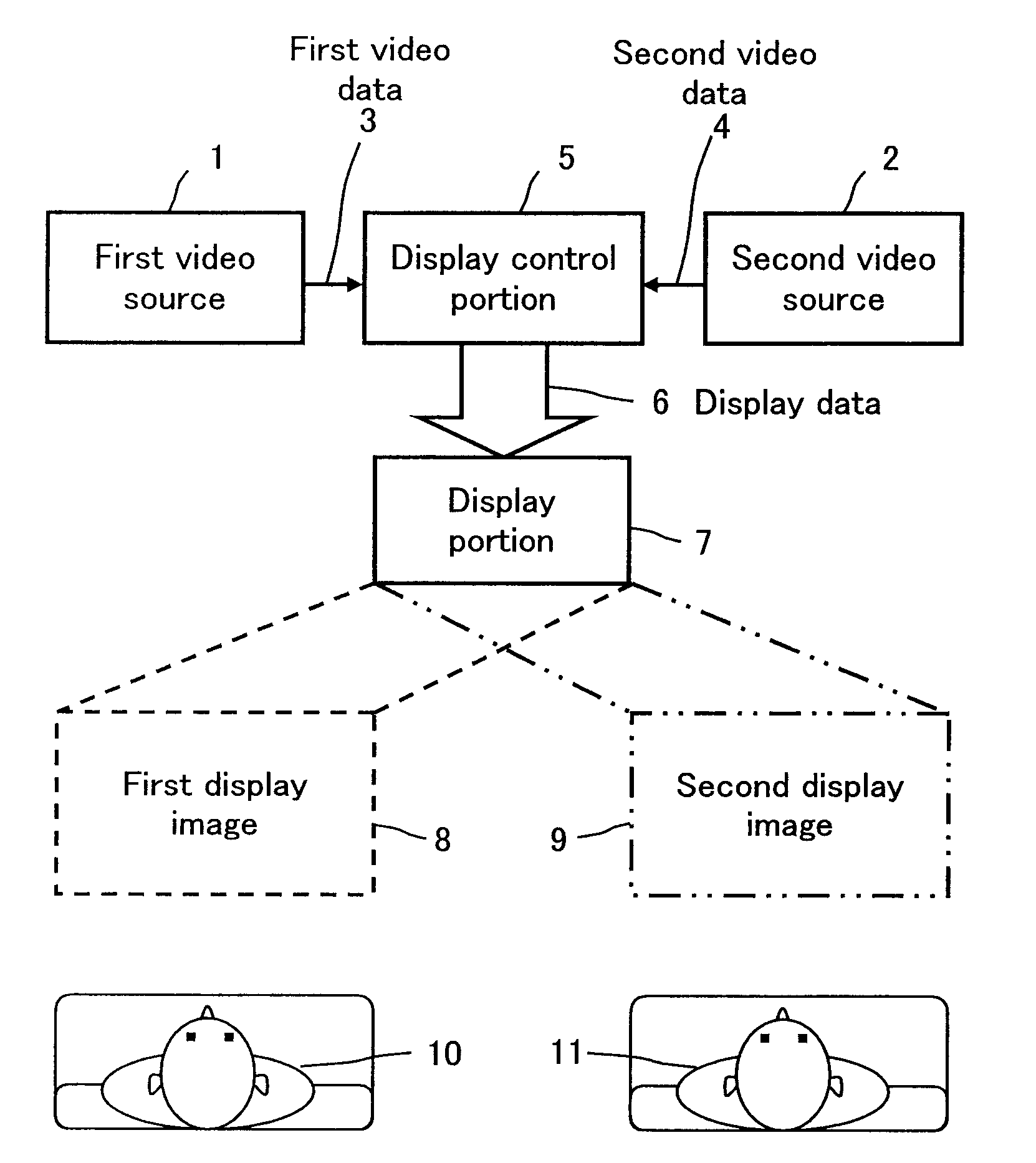
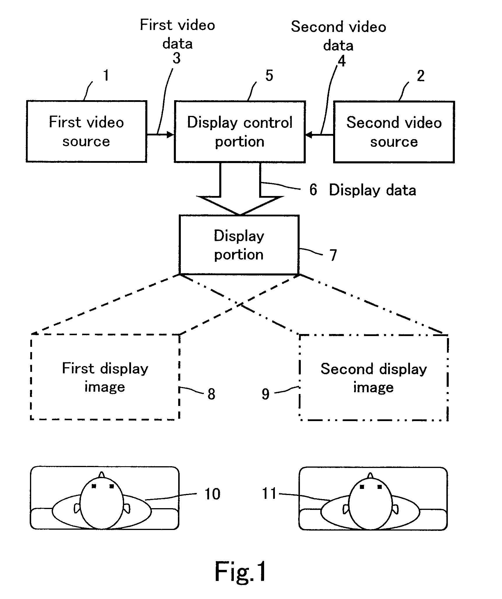
[0037]FIG. 1 is a schematic diagram of a dual view display device according to the present invention (hereinafter referred to as “display device”). In the figure, reference numeral 1 denotes a first video source, 2 denotes a second video source, 3 denotes first video data from the first video source, 4 denotes second video data from the second video source, 5 denotes a display control portion, 6 denotes display data, 7 denotes a display portion (e.g., a liquid crystal panel), 8 denotes a first display image based on the first video source 1, 9 denotes a second display image based on the second video source 2, 10 denotes a viewer (user) located to the left of the display portion 7, and 11 ...


PUM


Abstract

Provided are a cheap display device and a display method that are capable of preventing loss of high-frequency component during generation of a video signal from a source signal while at the same time securing continuity of pixel data.The display device includes a display portion 7 capable of displaying distinct videos on a common screen in a plurality of viewing directions and a video signal generating portion 300 for generating video signals by carrying out compression processing of video source signals for the viewing directions at predetermined compression rates. The video signal generating portion 300 generates new color components by using color components of a plurality of adjacent pixels aligned in a predetermined direction among pixels corresponding to the video source signals, and generates each of the video signals on the basis of a new pixel composed of the generated color components.

Description

[0001]This application is the U.S. national phase of international application PCT / JP2008 / 054353, filed on Mar. 11, 2008, which designated the U.S. and claims priority to JP Application No. 2007-066359, filed on Mar. 15, 2007. The entire contents of these applications are incorporated herein by reference.TECHNICAL FIELD[0002]The present invention relates to a display device including a display portion capable of displaying distinct videos on a common screen in a plurality of viewing directions and a video signal generating portion for generating video signals by carrying out compression processing of image data from video source signals for the viewing directions at predetermined compression rates.BACKGROUND ART[0003]Main developments of displays have thus far been drawn to optimization to enable a viewer to see a display from any directions with equally good image quality or to enable a plurality of viewers to obtain the same information simultaneously.[0004]However, there are many...

Claims


Application Information

Patent Timeline
IPC IPC(8): H04N5/445G02F1/133G09G3/20G09G3/36G09G5/00G09G5/02G09G5/36
CPCG02F1/1323G02F1/133524G02F2201/52H04N13/0409G09G3/3611G09G2340/0457G09G3/003H04N13/31
Inventor MINO, ATSUSHI
Owner FUJITSU GENERAL LTD
Learn More