Optical Lens System for Taking Image
- Summary
- Abstract
- Description
- Claims
- Application Information
AI Technical Summary
Benefits of technology
Problems solved by technology
Method used
Image

Examples
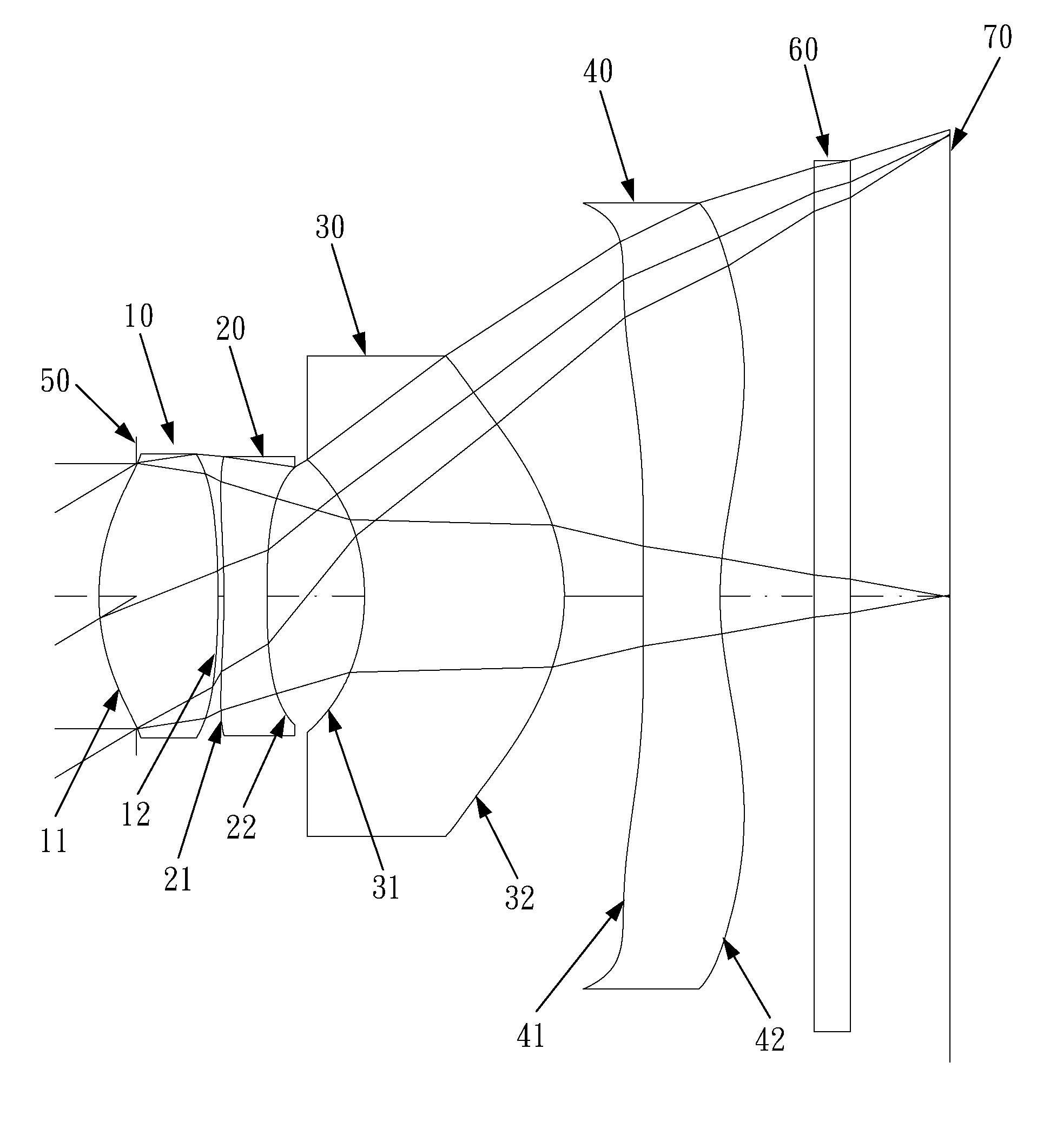
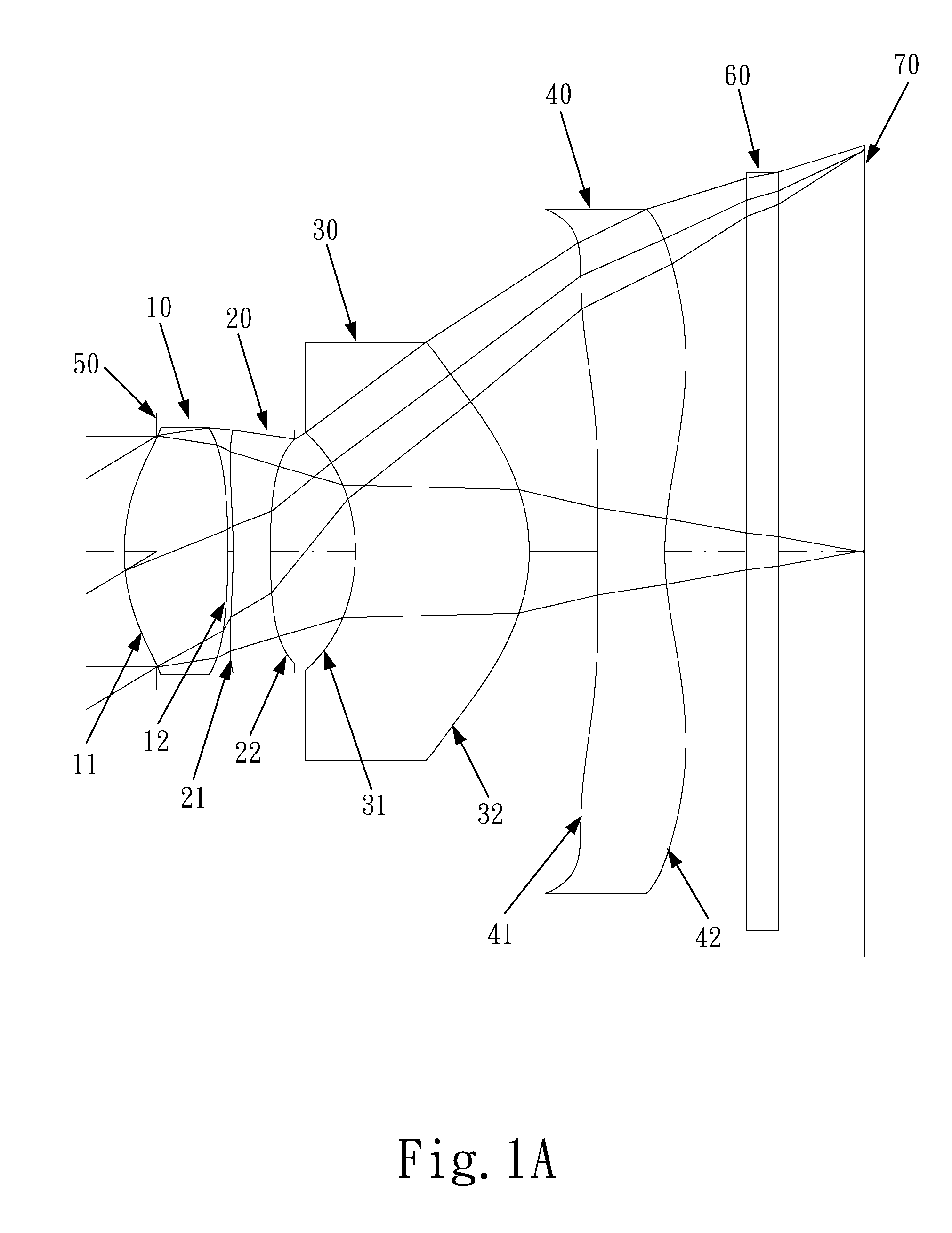
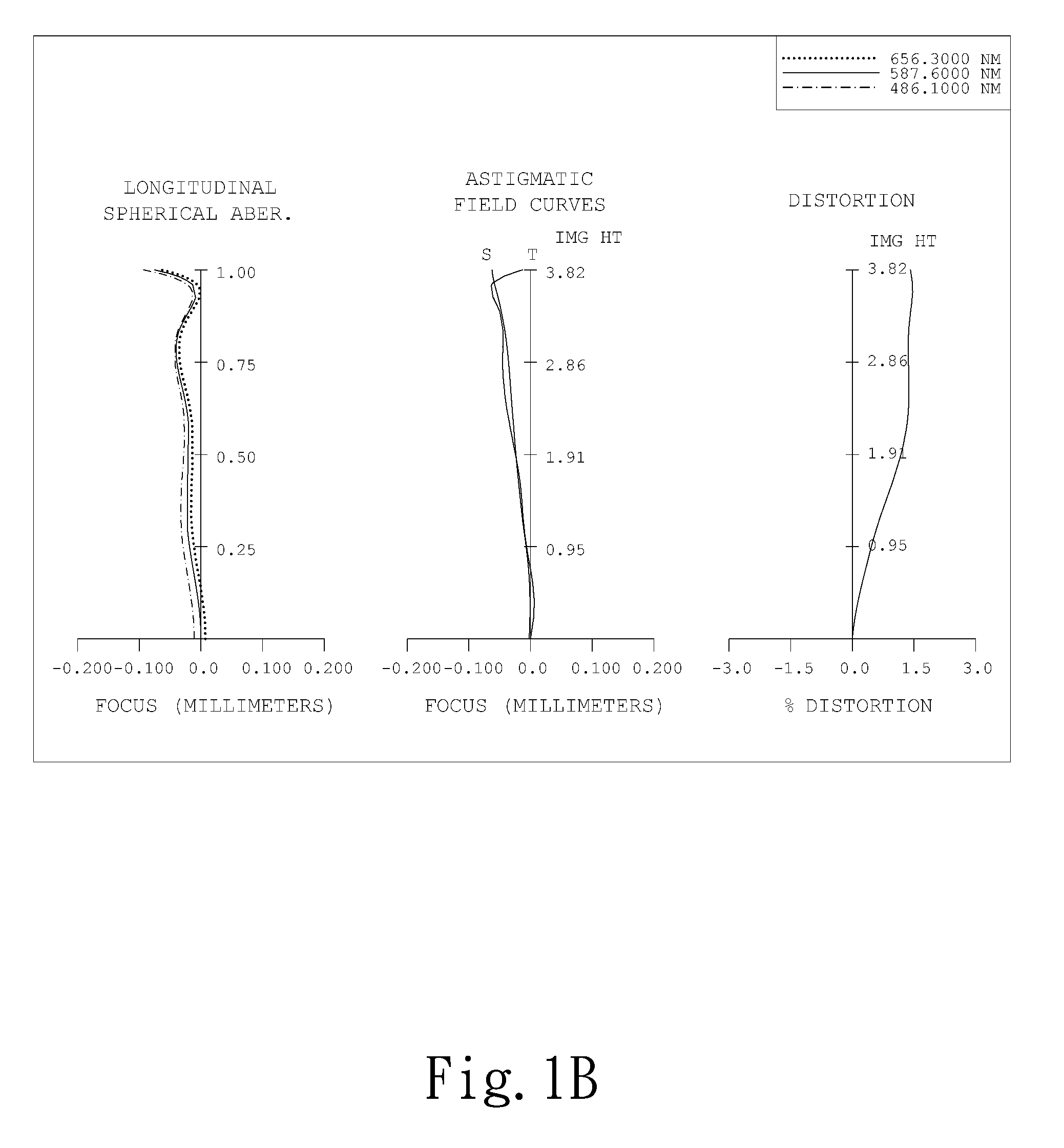
first embodiment
[0061]The equation for the aspheric surface profiles of the first embodiment is expressed as follows:
X(Y)=(Y2 / R) / (1+sqrt(1-(1+k)*(Y / R)2))+∑i(Ai)*(Yi)
[0062]wherein:
[0063]X: the height of a point on the aspheric lens surface at a distance Y from the optical axis relative to the tangential plane at the aspheric surface vertex;
[0064]Y: the distance from the point on the curve of the aspheric surface to the optical axis;
[0065]k: the conic coefficient;
[0066]Ai: the aspheric surface coefficient of order i.
[0067]In the first embodiment of the present optical lens system for taking image, the focal length of the optical lens system for taking image is f, the focal length of the first lens element is f1, the focal length of the third lens element is f3, the focal length of the fourth lens element is f4, the focal length of the first lens element and the second lens element combined is f12, the on-axis distance between the first lens element and the second lens element is T12, the on-axis dist...
second embodiment
[0082]In the present optical lens system for taking image, the focal length of the optical lens system for taking image is f, the focal length of the first lens element is f1, the focal length of the third lens element is f3, the focal length of the fourth lens element is f4, the focal length of the first lens element and the second lens element combined is f12, the on-axis distance between the first lens element and the second lens element is T12, the on-axis distance between the second lens element and the third lens element is T23, the on-axis distance between the third lens element and the fourth lens element is T34, and they satisfy the relations:
f=6.59 mm;
f / f12=1.29;
f / f1=2.32;
f / f3=0.62;
|f / f4|=0.84;
(T12 / f)*100=1.1;
(T23 / f)*100=15.7;
(T34 / f)*100=8.2.
[0083]In the second embodiment of the present optical lens system for taking image, the refractive index of the first lens element is N1, the refractive index of the second lens element is N2, and they satisfy the relations:
N1=1.544;
N2...
third embodiment
[0097]In the present optical lens system for taking image, the focal length of the optical lens system for taking image is f, the focal length of the first lens element is f1, the focal length of the third lens element is f3, the focal length of the fourth lens element is f4, the focal length of the first lens element and the second lens element combined is f12, the on-axis distance between the first lens element and the second lens element is T12, the on-axis distance between the second lens element and the third lens element is T23, the on-axis distance between the third lens element and the fourth lens element is T34, and they satisfy the relations:
f=5.93;
f / f12=0.96;
f / f1=1.70;
f / f3=1.23;
|f / f4|=1.11;
(T12 / f)*100=1.7;
(T23 / f)*100=19.1;
(T34 / f)*100=7.1.
[0098]In the third embodiment of the present optical lens system for taking image, the refractive index of the first lens element is N1, the refractive index of the second lens element is N2, and they satisfy the relations:
N1=1.544;
N2=1.6...
PUM
 Abstract
Description
Claims
Application Information
 - Generate Ideas
- Intellectual Property
- Life Sciences
- Materials
- Tech Scout
- Unparalleled Data Quality
- Higher Quality Content
- 60% Fewer Hallucinations
Browse by: Latest US Patents, China's latest patents, Technical Efficacy Thesaurus, Application Domain, Technology Topic, Popular Technical Reports.
© 2025 PatSnap. All rights reserved.Legal|Privacy policy|Modern Slavery Act Transparency Statement|Sitemap|About US| Contact US: help@patsnap.com