Emergency light station with mechanically activated radio frequency signaling

a technology of radio frequency signaling and emergency light, which is applied in the direction of lighting and heating equipment, transportation and packaging, and can solve the problems of difficulty in evacuation from a train or airplane wreck, difficulty in evacuating an area during an emergency, and loss of ambient lighting

Inactive Publication Date: 2010-04-22
CYALUME TECH
View PDF23 Cites 0 Cited by
  • Summary
  • Abstract
  • Description
  • Claims
  • Application Information

AI Technical Summary

Benefits of technology

[0035]Another object of this invention is to provide an emergency light station in which the electrical power source does not degrade as is the case with chemical batteries. Yet another object of this invention is to provide a means of deterring theft or vandalism of emergency light stations.

Problems solved by technology

The ability to evacuate an area during an emergency is often hampered by the loss of ambient lighting as well as artificial light.
For instance, evacuation from a train or airplane wreck will undoubtedly be made more difficult if no light is available.
In fact, the loss of lighting will typically cause a panic situation whether the emergency is a wreck, weather related, an earthquake, or simply a power grid failure.
Evacuation procedures require the individuals to leave an area, thus the fixed lighting system becomes ineffective.
Panic stricken individuals may refuse to leave a lighted area.
For instance, the evacuation during an earthquake may require individuals to leave a lighted area; the lack of lighting in the exit way may prevent an orderly and safe evacuation.
The survivors of a train or plane crash require the individuals to leave the area wherein a fixed light does not provide any mobile coverage.
Public transportation vehicles are especially at risk for inadequate lighting in an emergency situation because the power source is typically provided a battery which is continuously charged by the main power source of the vehicle.
In use, battery powered lights are obviously only as good as the battery.
If the battery has not been properly maintained or replaced, or becomes damaged during an accident, the battery powered light will fail.
Further, since chemiluminescent light production does not produce significant heat, these devices are not a source of ignition.
While placement of such systems in subway tunnels and on trains and in similar locations will greatly enhance the safety of these environments, should an emergency occur, two problems remain.
First, safety appliances which are located in public areas are sometimes subject to vandalism or deliberate misuse.
Some form of audible alarm or visible signaling means to indicate that the container had been opened could be used for this purpose, however, absent an observer; this would be of little use.
The second problem is that valuable time can be lost in a real emergency between the time that an individual container is opened, thereby possible signaling an emergency event, and the time that the emergency event is reported to those who must respond such as fire or police.
While this energy may be limited when compared to that produced by conventional chemical batteries such as alkaline or lithium cells, nevertheless this energy is sufficient to perform useful tasks.
While traditional electrochemical cells, commonly referred to as batteries, are frequently employed to power a variety of electrically operated devices, there are situations in which the use of such energy sources is prohibited or otherwise undesirable.
Similarly, fuel and / or cargo spills at accident sites may prevent the safe use of conventional energy supplies.
Additionally, use of traditional electrical energy sources in such atmospheres may require the use of explosion-proof fixtures and / or intrinsically safe wiring, both of which are costly to install.
Such sparks and heat could cause a fire or explosion in the presence of flammable gasses or vapors such as may be found in a train or plane crash.

Method used


Image

  • Emergency light station with mechanically activated radio frequency signaling
  • Emergency light station with mechanically activated radio frequency signaling
  • Emergency light station with mechanically activated radio frequency signaling

Examples


Embodiment Construction

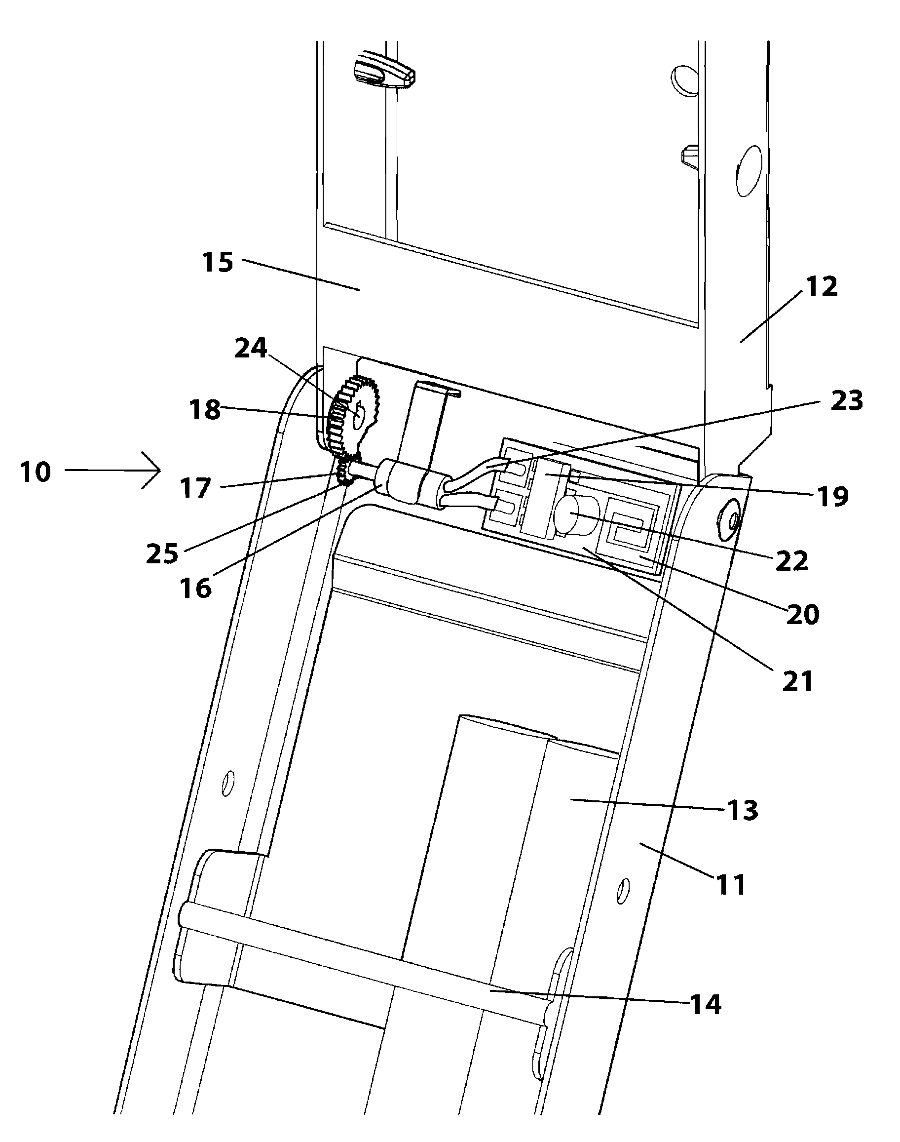
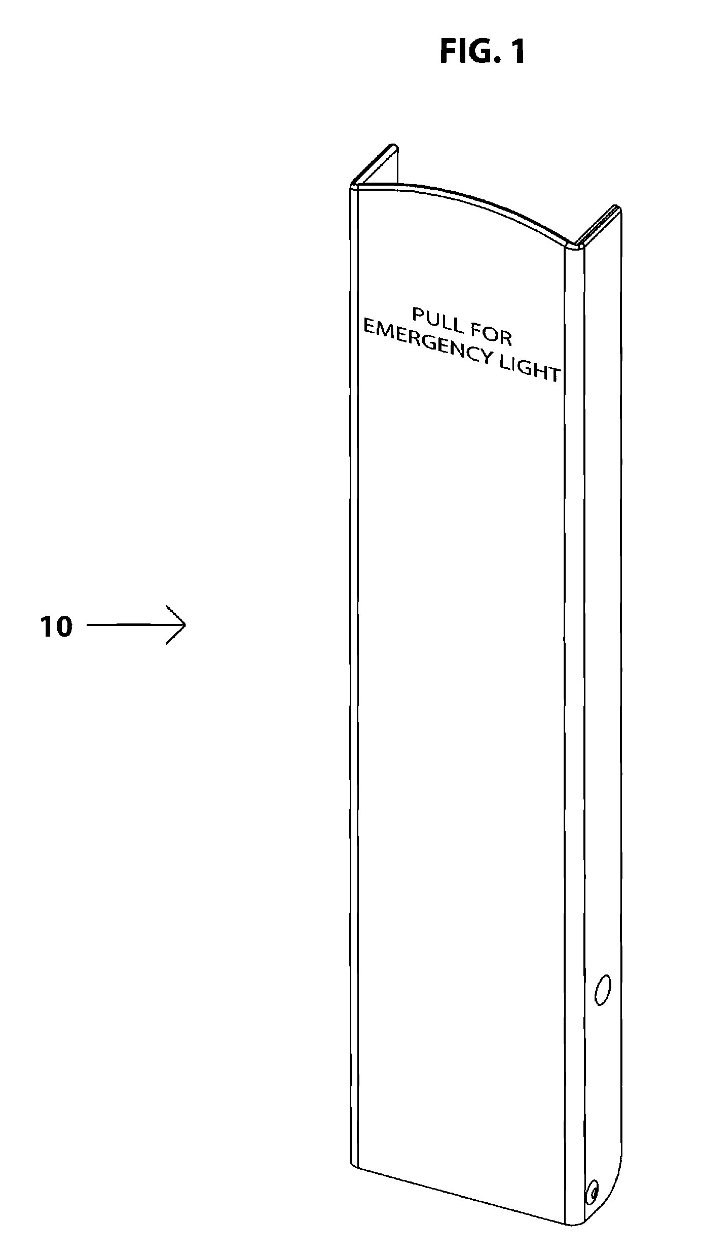
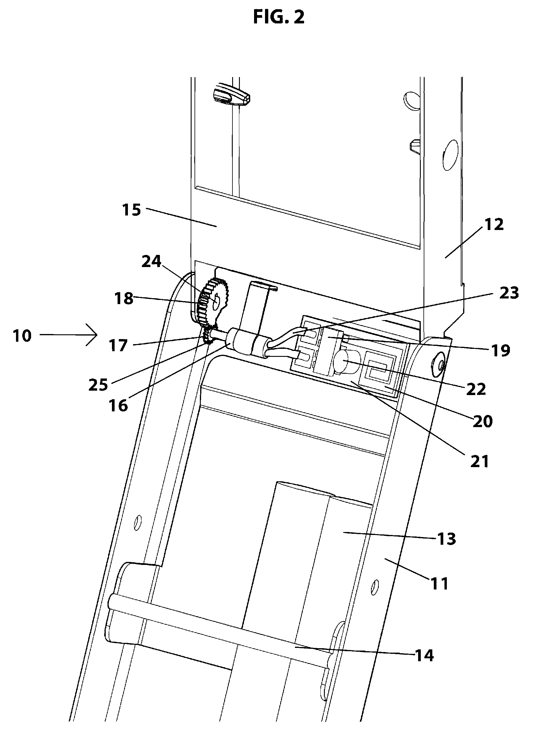
[0044]Referring to FIG. 1, an emergency light station (10) with radio frequency signaling is provided. As previously described the light station contains a plurality of lightsticks. When the container cover is opened, a portion of these lightsticks are automatically activated and made available to the user. Before opening, the light sticks are protected by the container from light exposure, accidental activation and theft. Now, referring to FIG. 2, Front cover (11) is hinged with respect to mounting base (12). Upon opening, chemiluminescent lightstick(s) (13) which are disposed in the container are submitted to a bending force created by interaction of breaker bar (14) and retainer plate (15). At some point, the force on chemiluminescent lightstick (13) is sufficient to cause it to be activated. Gear (18), is non-rotatably attached to mounting base hinge pin (24), said pin being non-rotatably attached to mounting base (12).

[0045]Gear (18) meshes with drive gear (17) and causes drive...


PUM


Abstract

A signaling system for an emergency light station containing chemiluminescent light sticks. The light station includes a cover that generates mechanical energy upon opening that is then transformed into electrical power. The electrical power is then utilized to transmit a radio frequency signal to a remote location is alert an observer to the fact that the light station has been opened. The alert provides an immediate indication that an emergency is in progress or that the safety emergency light station is being vandalized.

Description

RELATED APPLICATIONS[0001]This application is related to patent application Ser. No. 11 / 875,371 filed Oct. 19, 2007 and Ser. No. 12 / 017,577 filed Jan. 22, 2008.BACKGROUND OF THE INVENTION[0002]The ability to evacuate an area during an emergency is often hampered by the loss of ambient lighting as well as artificial light. For instance, evacuation from a train or airplane wreck will undoubtedly be made more difficult if no light is available. In fact, the loss of lighting will typically cause a panic situation whether the emergency is a wreck, weather related, an earthquake, or simply a power grid failure. When the evacuation includes numerous people, it is a necessity to stop panic and evacuate in an orderly manner for the safety of all involved. For these reasons, the need for emergency lighting is mandatory under most building codes.[0003]Emergency lighting typically takes the form of fixed lighting powered by an AC source with a DC back-up battery. The reliability of a fixed syst...

Claims


Application Information

Patent Timeline
Patent Type & Authority Applications(United States)
IPC IPC(8): F21K2/06F21V15/01
CPCF21L17/00F21V15/005F21V15/00
Inventor PALMER, WILLIAM R.PALMER, STEPHEN L.LONGO, JOSEPH COSIMODOMINGOS, ERIC JAMES
Owner CYALUME TECH
Why Eureka
Try Eureka