Performance monitoring in passive optical networks

a performance monitoring and passive optical network technology, applied in the field of passive optical network, can solve the problems of dsl or cm technology, limited bandwidth offered by current access networks, and difficulty in providing integrated services

Active Publication Date: 2010-04-22
AVAGO TECH INT SALES PTE LTD
View PDF14 Cites 98 Cited by
  • Summary
  • Abstract
  • Description
  • Claims
  • Application Information

AI Technical Summary

Benefits of technology

[0024]In a variation on the embodiment, the performance monitoring mechanism is further configured

Problems solved by technology

Even with broadband solutions, such as digital subscriber line (DSL) and cable modem (CM), the limited bandwidth offered by current access networks st

Method used


Image

  • Performance monitoring in passive optical networks
  • Performance monitoring in passive optical networks
  • Performance monitoring in passive optical networks

Examples


examples

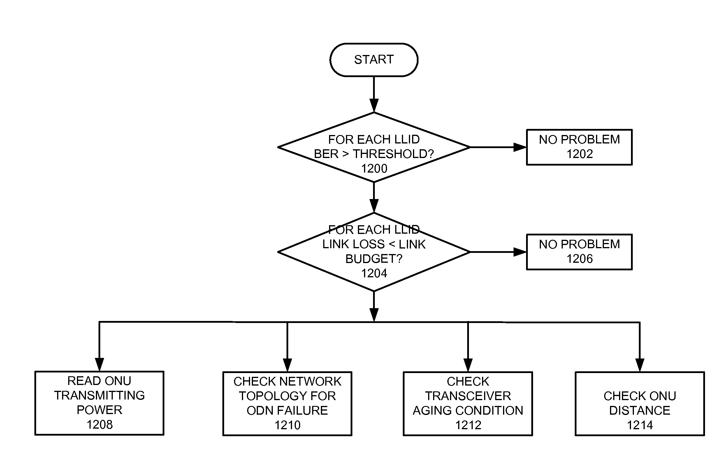
[0082]Power-monitoring-based and BER-based performance monitoring methods can be used independently or can be combined to detect and diagnose faults in a PON. Excessive BER often indicates the early phase of a potential fault in an underlying physical layer, including the optical transceiver and the ODN. Power monitoring can be used to further validate and isolate the problem. For example, it can determine whether the problem is intermittent or persistent, whether the problem is caused by faults in optical transceivers on an OLT or on an ONU, and whether the problem is caused by faults in the ODN. The following fault detection examples are given to describe the performance monitoring system better.

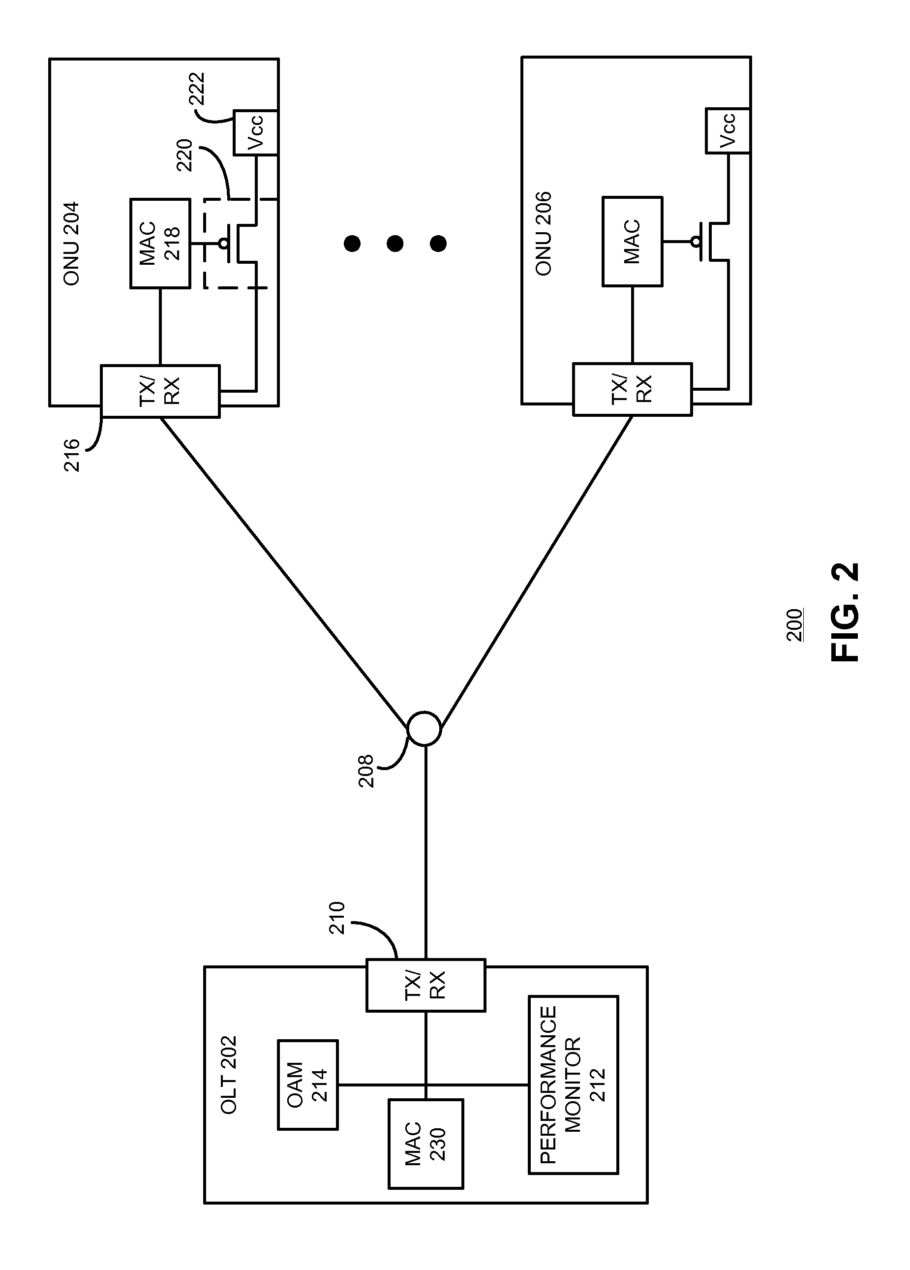
[0083]In one example, one of the ONU's transmitters is “stuck” on, which means it continues to transmit power even though no grant is given to the ONU. To detect that this condition is occurring on the PON interface, the system first determines whether the measured OLT receiving power duri...


PUM


Abstract

One embodiment provides a system for performance monitoring in a passive optic network (PON). The system includes an optical line terminal (OLT) and an optical network unit (ONU). The OLT includes an optical transceiver configured to transmit optical signals to and receive optical signals from the ONU, and a performance monitoring mechanism configured to monitor performance of the PON based on received optical signals.

Description

RELATED APPLICATION[0001]This application claims the benefit of U.S. Provisional Application No. 61 / 107,255, Attorney Docket Number TEK08-1005PSP, entitled “Optical Monitoring in Passive Optical Networks,” by inventors Rick W. Li and Jaroslaw Wojtowicz, filed 21 Oct. 2008.BACKGROUND[0002]1. Field[0003]This disclosure is generally related to a passive optical network (PON). More specifically, this disclosure is related to performance monitoring in a PON.[0004]2. Related Art[0005]In order to keep pace with increasing Internet traffic, network operators have widely deployed optical fibers and optical transmission equipment, substantially increasing the capacity of backbone networks. A corresponding increase in access network capacity is also needed to meet the increasing bandwidth demand of end users for triple play services, including Internet protocol (IP) video, high-speed data, and packet voice. Even with broadband solutions, such as digital subscriber line (DSL) and cable modem (C...

Claims


Application Information

Patent Timeline
IPC IPC(8): H04B10/08H04B10/2581H04J14/00
CPCH04B10/0795H04J3/1694H04B10/07H04B10/07955H04Q2011/0083H04B10/07953H04Q11/0067H04L1/0045H04L1/203
Inventor LI, WEIDONG RICKWOJTOWICZ, JAROSLAW
Owner AVAGO TECH INT SALES PTE LTD
Why Eureka
Try Eureka