Method of operating ice making machine

a technology of ice making machine and ice-making water tank, which is applied in the field of ice-making machine operation, can solve the problems of reducing ice-making performance, reducing ice-making performance, and wasting water resources, and achieves the effect of efficient production

Active Publication Date: 2010-04-29
HOSHIZAKI ELECTRIC CO LTD
View PDF10 Cites 15 Cited by
  • Summary
  • Abstract
  • Description
  • Claims
  • Application Information

AI Technical Summary

Benefits of technology

[0014]According to the method of operating an ice making machine of the invention, clean ice blocks can be efficiently produced by performing the water-discharge operation.

Problems solved by technology

That is, it is pointed out that the ice making machine stands by with ice-making water remaining in the ice-making water tank, bringing about problems of deposition of an impurity in the ice-making water tank and breeding of bacteria.
When such an operation is performed, the ice-making operation cannot be started immediately after the standby state, resulting in reduction in ice-making performance.
When the deicing operation is completed, however, a large amount of ice-making water is stored in the ice-making water tank at the ice-making start water level, and it takes a longer time to discharge water as compared with the case of discharging a small amount of ice-making water at the ice-making completion water level after completion of the ice-making operation as mentioned above.
This makes the discharge time longer, so that even when ice blocks are consumed, the water-discharge operation is not completed and the operation cannot be shifted to the ice-making operation.
This brings about a problem of degrading the ice-making performance of the ice making machine per unit time.

Method used


Image

  • Method of operating ice making machine
  • Method of operating ice making machine
  • Method of operating ice making machine

Examples


embodiment

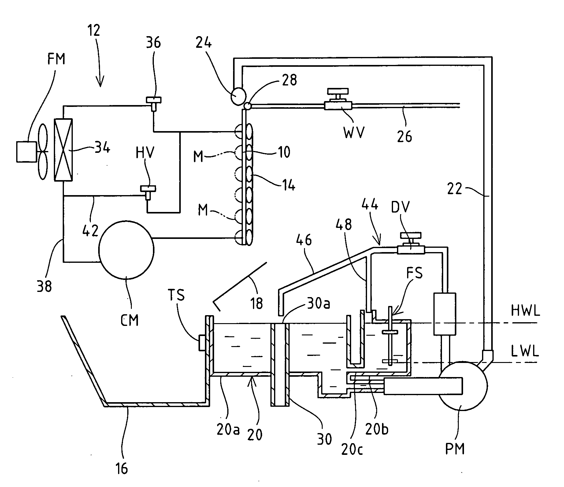
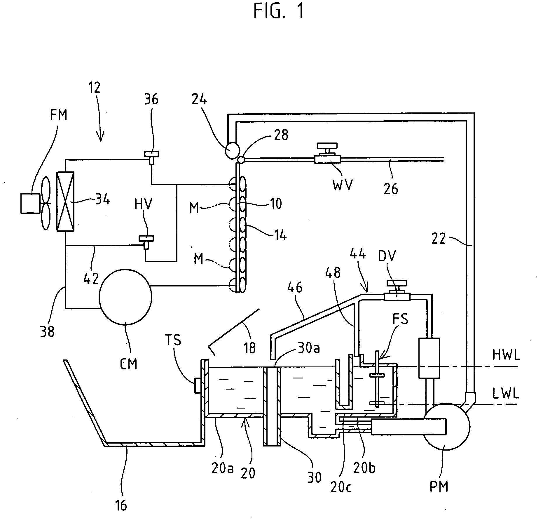
[0022]A down flow type ice making machine as shown in FIG. 1 is configured to basically repeat an ice-making operation of producing ice blocks M and a deicing operation of separating the produced ice blocks M (see FIG. 5), and perform a water-discharge operation of discharging ice-making water outside from an ice-making water tank 20 by using water discharge means 44 at an adequate timing. According to the embodiment, the water-discharge operation is performed in every predetermined cycle between the ice-making operation and the deicing operation and after completion of the deicing operation when a full-of-ice state in an ice storage chamber 16 is detected. Note that the water-discharge operation which is performed between the ice-making operation and the deicing operation is called “normal water-discharge operation” and the water-discharge operation which is performed in case of detecting a full-of-ice state in the ice storage chamber 16 is called “special water-discharge operation...


PUM


Abstract

A method of operating an ice making machine efficiently provides clean ice blocks. A special water-discharge operation which is performed when an ice storage switch (TS) provided at an ice storage chamber (16) storing ice blocks (M) separated in a deicing operation detects that the ice storage chamber (16) is full of ice discharges the ice-making water from the ice-making water tank (20) via water discharge means (44) by releasing a water discharge valve (DV) provided at the water discharge means (44). Then, the special water-discharge operation is terminated by closing the water discharge valve (DV) when a preset duration time (T) passes after a float switch (FS) provided at the ice-making water tank (20) detects an ice-making completion water level (LWL) of the ice-making water in the ice-making water tank (20) after discharge of the ice-making water to outside is started.

Description

TECHNICAL FIELD[0001]The present invention relates to a method of operating an ice making machine, which performs a water-discharge operation of discharging ice-making water from an ice-making water tank via water discharge means communicating with the outside.BACKGROUND ART[0002]A down flow type ice making machine is widely used as an ice making machine to produce a large quantity of ice blocks for its simple configuration and low ice-making cost. The down flow type ice making machine is configured in such a way that an evaporation pipe led out from a freezing apparatus is disposed at an ice making part provided upright vertically, and ice-making water is sprayed onto the ice making part cooled by a refrigerant which flows in the evaporation pipe in an ice-making operation, thereby producing ice blocks. The ice making machine is configured to have an ice-making water tank to store ice-making water, so that at the time of the ice-making operation, the ice-making water in the ice-mak...

Claims


Application Information

Patent Timeline
Patent Type & Authority Applications(United States)
IPC IPC(8): F25C1/00
CPCF25C1/225F25C5/187F25C2400/12F25C1/12F25C2600/02F25C2700/04F25C2400/14F25C1/25
Inventor YOSHIDA, KAZUHIROWAKATSUKI, YUJIOHTA, HIDEJIYAMAGUCHI, HIROKIYONEKURA, YUSHI
Owner HOSHIZAKI ELECTRIC CO LTD
Why Eureka
Try Eureka