Eureka AIR delivers breakthrough ideas for toughest innovation challenges, trusted by R&D personnel around the world.

Unlocking structure and connector holding structure

Active Publication Date: 2010-04-29
INVENTEC CORP
View PDF5 Cites 6 Cited by
  • Summary
  • Abstract
  • Description
  • Claims
  • Application Information

AI Technical Summary

Benefits of technology

[0008]Accordingly, the present invention is directed to an unlocking structure and a connector holding structure, for conveniently unlocking a hook and installing a connector.
[0019]In the unlocking structure of the present invention, through the interference between the guiding inclined plane and the elastic arm of the locking element, the hook of the locking element is unlocked, so the operation is quite simple and convenient. In addition, through the connector holding structure of the present invention, the connector is installed on the frame through the board element. Therefore, in the present invention, the installation of the connector is much more convenient.

Problems solved by technology

However, as an inner space of the computer case is limited, hands of the user difficultly move in the case, such that the connector is hard to be aligned with the slot.
Therefore, insertion and extraction of the connector are quite inconvenient.

Method used


Image

  • Unlocking structure and connector holding structure
  • Unlocking structure and connector holding structure
  • Unlocking structure and connector holding structure

Examples


Embodiment Construction

[0024]Reference will now be made in detail to the present embodiments of the invention, examples of which are illustrated in the accompanying drawings. Wherever possible, the same reference numbers are used in the drawings and the description to refer to the same or like parts.

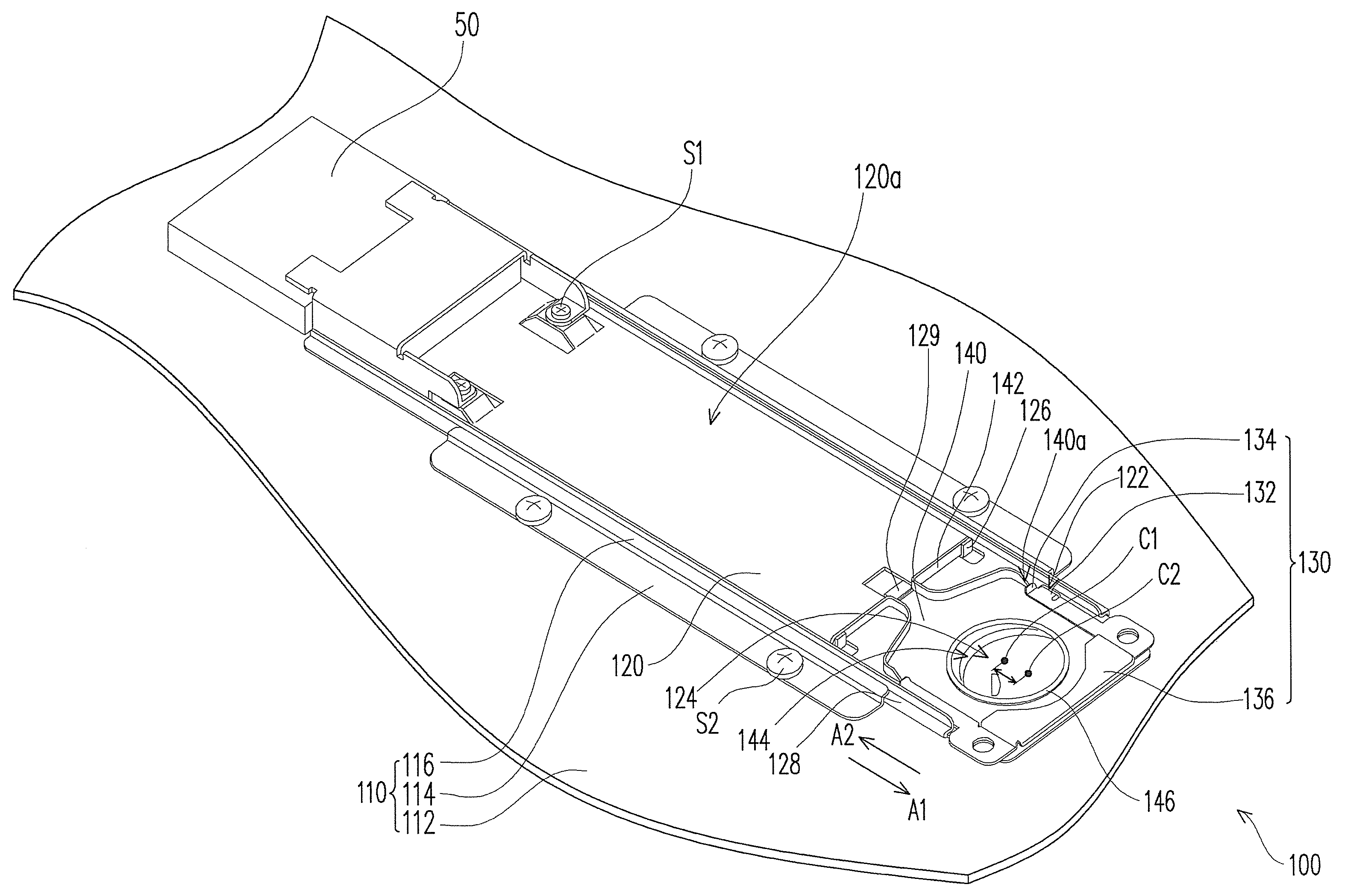
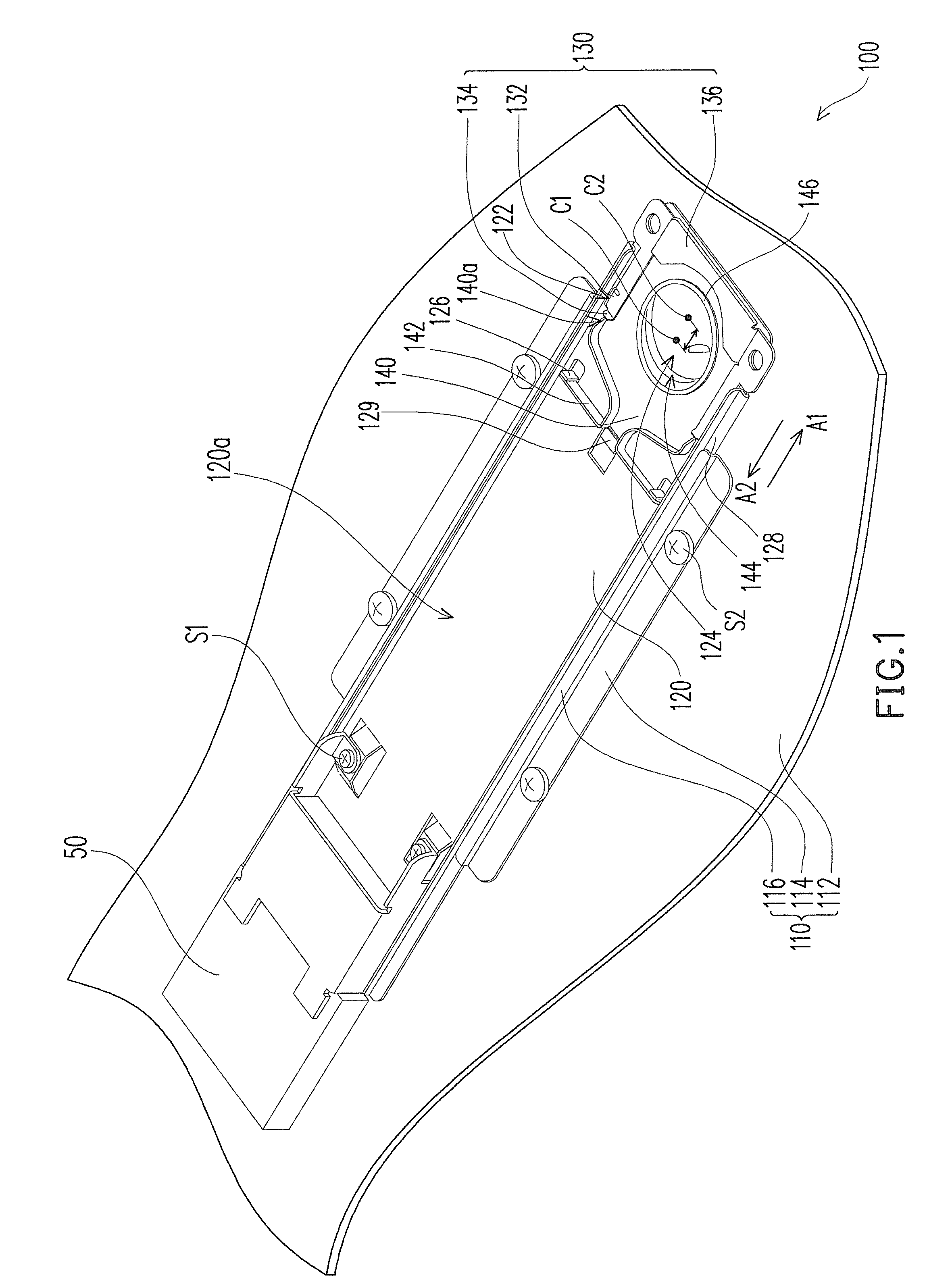
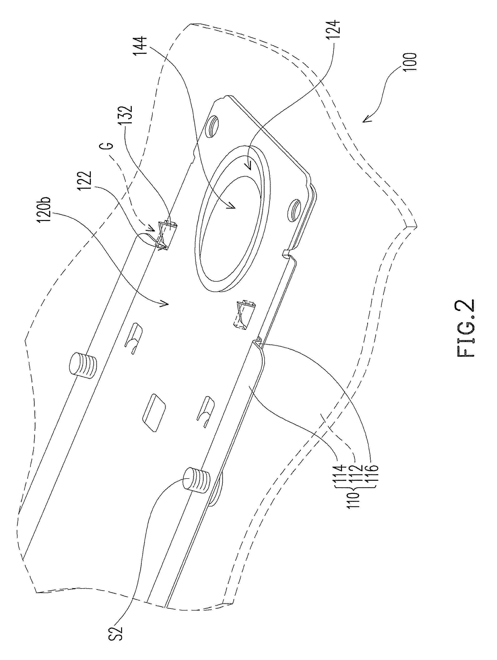
[0025]FIG. 1 is a three-dimensional view of a connector holding structure according to an embodiment of the present invention, and FIG. 2 is a partial three-dimensional view of the holding structure of FIG. 1 from another view of angle. Referring to FIGS. 1 and 2, a holding structure 100 mainly includes a frame 110, a board element 120, a locking element 130, and a guiding element 140. The holding structure 100 is suitable to hold a connector 50. In this embodiment, the connector 50 may be fixed on the board element 120 through a plurality of screws S1, such that the connector 50 may be driven by the board element 120 to be installed in a slot of a storage device (not shown) or a circuit board (not shown).

[002...


PUM


Abstract

An unlocking structure including a board element, a locking element, and a guiding element is provided. The board element has a first surface, a second surface, and at least one first opening. The locking element with at least one hook and at least one first elastic arm is disposed on the first surface of the board element. The hook is connected to the first elastic arm and passes through the first opening to protrude from the second surface of the board element. The guiding element is slidingly disposed on the first surface of the board element and is located between the board element and the locking element. The guiding element has at least one guiding inclined plane. The guiding inclined plane is suitable to structurally interfere with the first elastic arm, so as to drive the hook to exit from the second surface towards the first surface.

Description

CROSS-REFERENCE TO RELATED APPLICATION[0001]This application claims the priority benefit of Taiwan application serial no. 97140698, filed on Oct. 23, 2008. The entirety of the above-mentioned patent application is hereby incorporated by reference herein and made a part of specification.BACKGROUND OF THE INVENTION[0002]1. Field of the Invention[0003]The present invention generally relates to a holding structure, in particular, to a connector holding structure.[0004]2. Description of Related Art[0005]In the current information multimedia time, computers undoubtedly become one of the necessities in our life and work. Servers, workstations, desktop computers, notebook computers, or even industrial computers have become the indispensable important tools.[0006]Generally, a computer may substantially include a host part, a display, and peripheries. The host part includes a computer case, and electronic elements disposed in the computer case, such as a main board, a central processing unit,...

Claims


Application Information

Patent Timeline
IPC IPC(8): E05B73/00
CPCG06F1/183Y10S292/63Y10T70/5009Y10T292/0894Y10T292/0898
Inventor HSU, YUNG-CHIN
Owner INVENTEC CORP
Why Eureka
Eureka Blog
Learn More