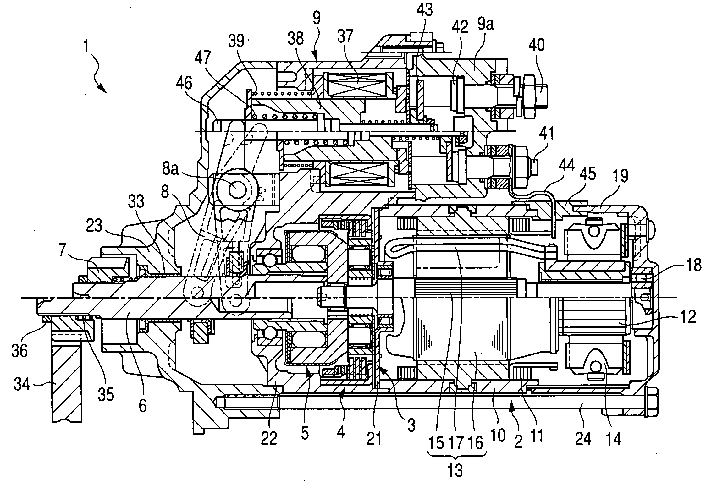
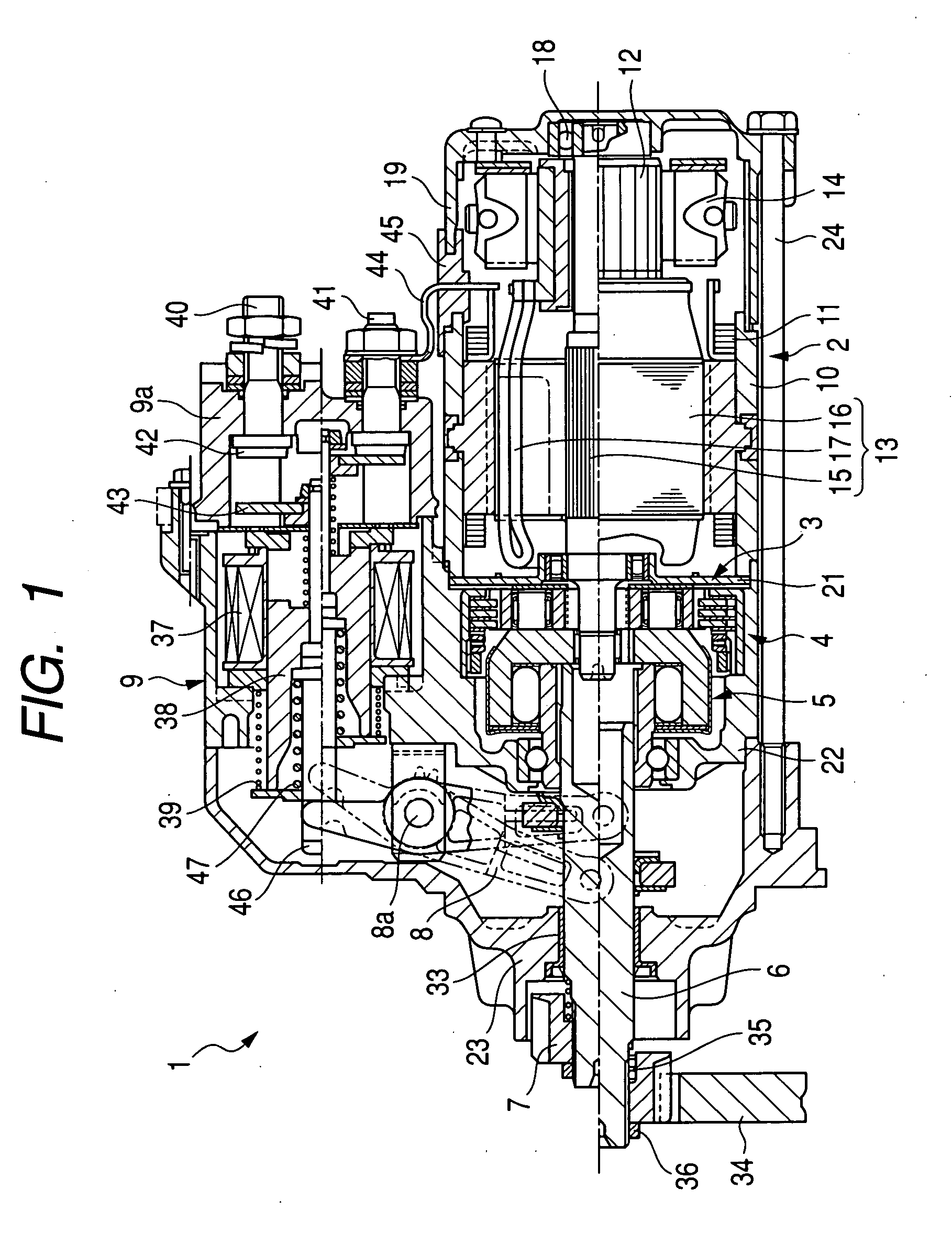
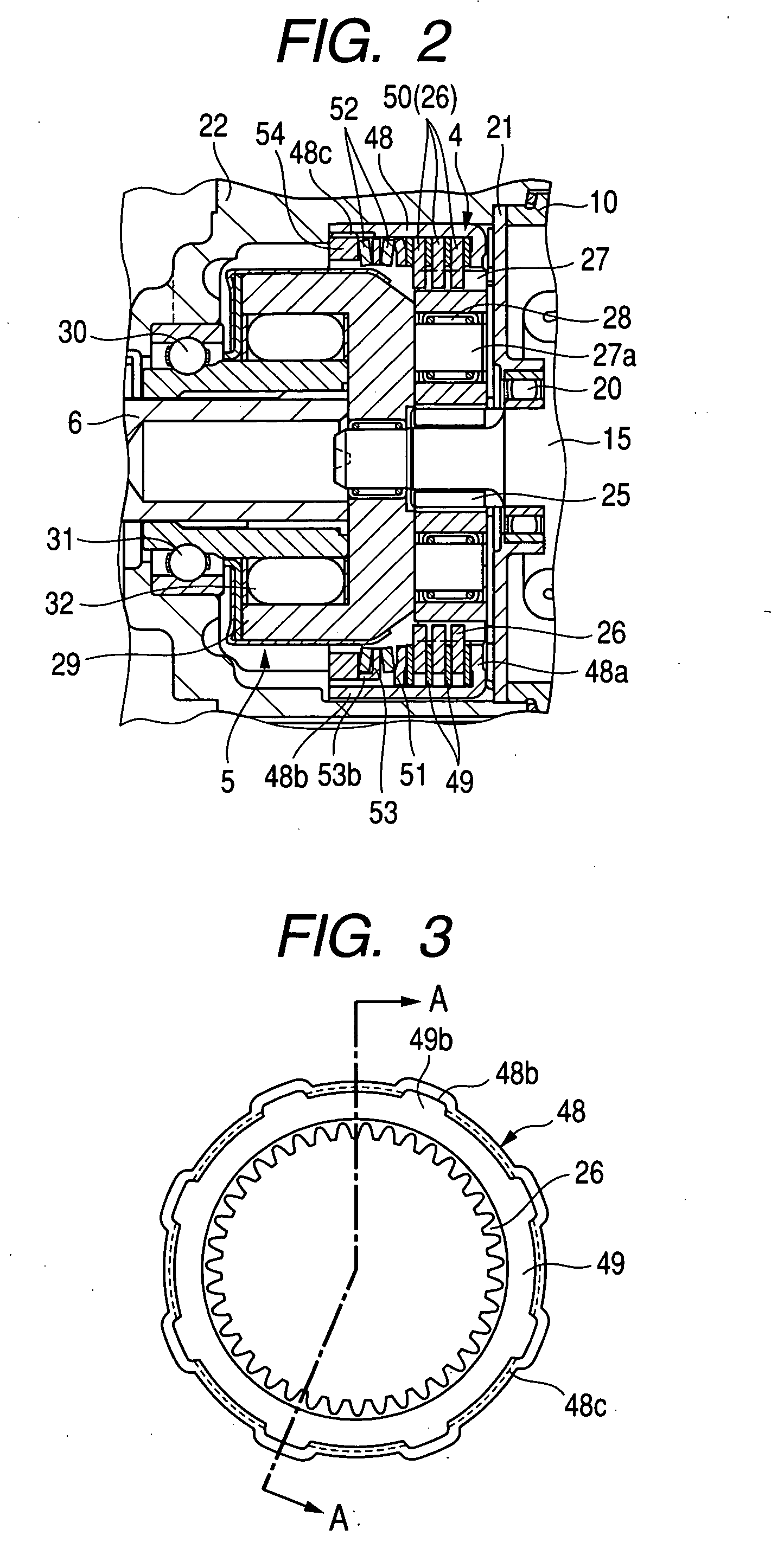
Starter equipped with planetary speed reducer and shock absorber

Active Publication Date: 2010-04-29
DENSO CORP
View PDF7 Cites 3 Cited by
  • Summary
  • Abstract
  • Description
  • Claims
  • Application Information

AI Technical Summary

Benefits of technology

[0021]The first and second load applying mechanisms are located on opposed sides of the adjacent member. The plate as the adjacent member may have formed therein recesses as the restraining mechanism in which the first and second load applying mechanism are retained and restrained from moving in the radius direction of the internal thread, thereby avoiding the undesirable engagement of the first and second load applying mechanisms with the internal gear.
[0022]The first and second load applying mechanisms are restrained from moving in the radius direction of the internal gear by the restraining mechanism so as to be centered to the case of the shock absorber. This results in coincidence between portions of the first and second load applying mechanisms which are placed in abutment with the plate, thereby minimizing the bias of load, as produced by the load adjuster, to achieve a high degree of efficiency of transmitting the load to the stati

Problems solved by technology

In such an event, the pressure, as produced by tightening the nut, will concentrate at portions of the disc spring and the internal gear caught by each other, which leads to a concern about a lack of application of elastic pressure of the disc springs to the stack of the stationary and rotary discs.
Add

Method used


Image

  • Starter equipped with planetary speed reducer and shock absorber
  • Starter equipped with planetary speed reducer and shock absorber
  • Starter equipped with planetary speed reducer and shock absorber

Examples


Example

[0080]The starter 1 of the second embodiment will be described below.

Example

[0081]The shock absorber 4 of the first embodiment, as described above, restrains one of the disc springs 52 which is located closer to the nut 54 from moving in the radius direction thereof. The shock absorber 4 of the second embodiment is designed to restrains both the disc springs 52 from moving in the radius direction.

[0082]Specifically, the protrusions 53a of the washer 53, as illustrated in FIG. 7, are bent in a direction opposite that in which the claws 53b extend, that is, toward the internal gear 26 to form, as illustrated in FIG. 9, claws 53c in addition to the claws 53b. In other words, the protrusions 53a of the washer 53 are broken down into a first group of the claws 53b and a second group of the claws 53c. The first group of the claws 53b extend in one of opposite axial directions of the washer 53 (i.e., opposite axial directions of the output shaft 6, while the second group of the claws 53c extend in the other axial direction. The claws 53b, like in the first embodim...

Example

[0085]The starter 1 of the third embodiment will be described below.

[0086]The shock absorber 4 of the second and third embodiments is designed to hold the disc spring(s) 52 from moving in the radius direction thereof using the claws 53b and / or 53c. The shock absorber 4 of this embodiment is designed to have annular grooves 53d, as illustrated in FIGS. 11(a), 11(b), and 11(c), formed in major surfaces of the washer 53 facing the disc springs 52. Specifically, the annular grooves 53d are formed by, for example, a press coaxially in the opposed surfaces of the washer 53. The disc springs 52, as clearly illustrated in FIG. 11(c), have inner circumferential corners or edges which face each other in the axial direction of the washer 53 and are fit in the annular grooves 53d to restrain the disc springs 52 from moving in the radius direction thereof.

[0087]The engagement of the circumferential edges of the disc springs 52 with the annular grooves 53d of the washer 53, like in the first and ...


PUM


Abstract

A starter for an engine is equipped with a planetary gear speed reducer, a restraining mechanism, and a shock absorber which is made up of a rotary disc, a stationary disc, a case, and a load applying mechanism. The load applying mechanism applies a load to the stationary and rotary discs to develop a given degree of friction therebetween. When an excessive torque acts on the rotary disc through the internal gear, the shock absorber induces the rotary disc to rotate against the given degree of friction to absorb the torque to eliminate a physical impact to be exerted on the planetary gear speed reducer. The restraining mechanism restrains the load applying mechanism from moving in a radius direction of the internal thread to avoid undesirable engagement of the load applying mechanism with the internal thread, thereby ensuring the stability in applying the load to the stationary and rotary discs.

Description

CROSS REFERENCE TO RELATED DOCUMENT[0001]The present application claims the benefit of Japanese Patent Application No. 2008-274123 filed on Oct. 24, 2008, the disclosure of which is incorporated herein by reference.BACKGROUND OF THE INVENTION[0002]1. Technical Field of the Invention[0003]The present invention relates generally to a starter designed to start engines such as automotive internal combustion engines, and more particularly to such a starter equipped with a planetary gear speed reducer and a shock absorber working to absorb impact torque acting on the starter which will arises upon cranking of the engine.[0004]2. Background Art[0005]Japanese Patent First Publication No. 2008-223572, assigned to the same assignee as that of this application, discloses a starter equipped with a multi-disc type shock absorber which includes a plurality of rotary discs formed integrally with an internal gear of a planetary gear speed reducer, a plurality of stationary discs each of which is di...

Claims


Application Information

Patent Timeline
IPC IPC(8): F02N15/02
CPCY10T74/137F02N15/046F02N15/063
Inventor USAMI, SHINJIKAJINO, SADAYOSHIHASEGAWA, YOUICHI
Owner DENSO CORP
Why Eureka
Try Eureka