Clutch assembly for a drive train and gear system comprising such a coupling assembly

A technology for clutch components and drive trains, applied in electric clutches, fluid-driven clutches, mechanical-driven clutches, etc., can solve problems such as loss, and achieve the effects of low performance loss, minimized resistance loss, and high efficiency

Active Publication Date: 2018-08-07
GKN DRIVELINE BRUNECK
View PDF10 Cites 3 Cited by
  • Summary
  • Abstract
  • Description
  • Claims
  • Application Information

AI Technical Summary

Problems solved by technology

On the other hand, high oil volume flow leads to drag moments and thus undesired losses

Method used


Image

  • Clutch assembly for a drive train and gear system comprising such a coupling assembly
  • Clutch assembly for a drive train and gear system comprising such a coupling assembly
  • Clutch assembly for a drive train and gear system comprising such a coupling assembly

Examples


Embodiment Construction

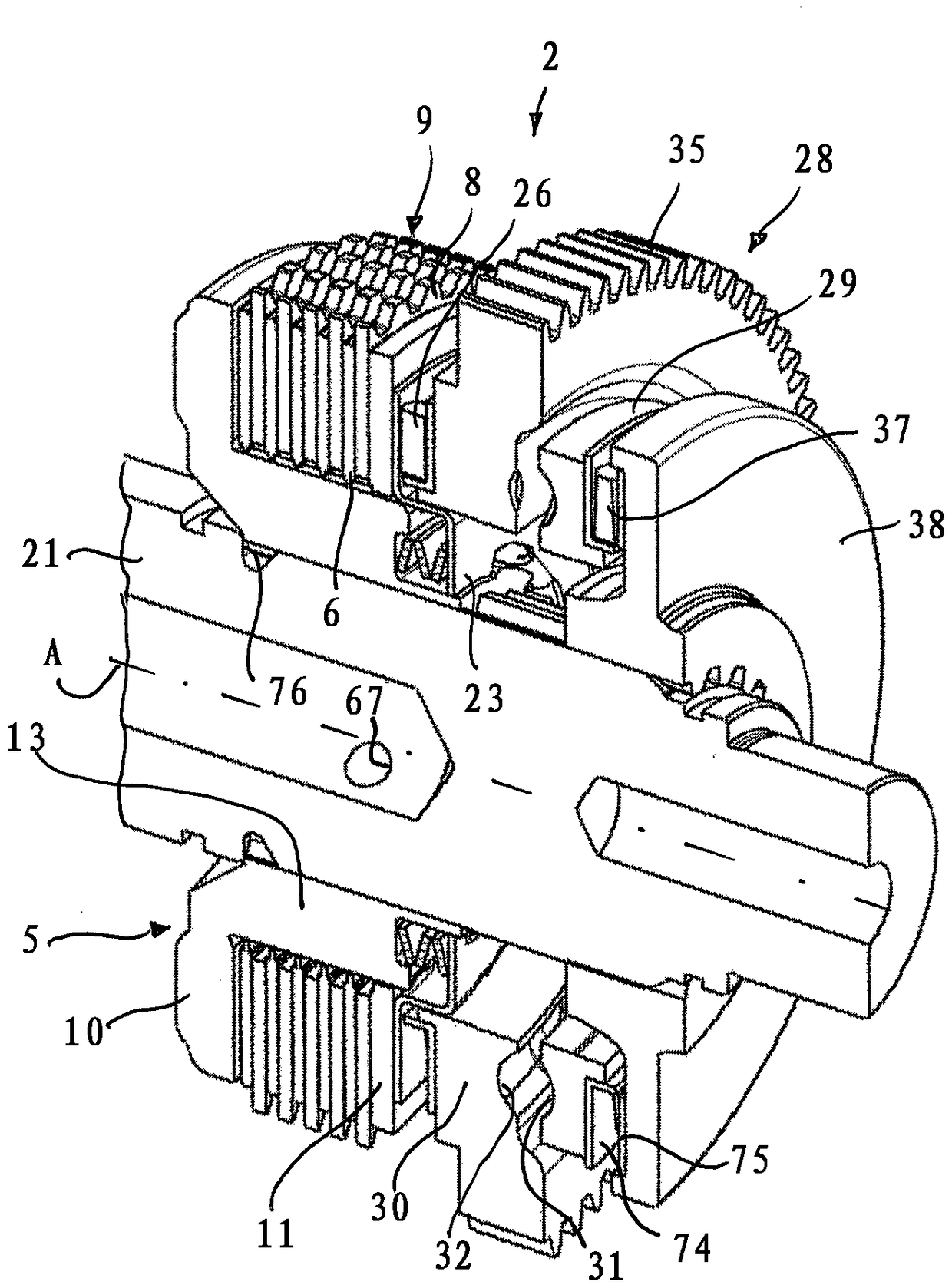
[0115] will describe together Figure 1 to Figure 6 A clutch assembly 2 of the invention for a drive train of a motor vehicle is shown. The clutch pack 2 comprises a friction plate clutch 3, and an operating device 4 for controlling the torque transmitted by the friction plate clutch. The friction plate clutch 3 is cooled and lubricated and can therefore also be referred to as a wet clutch. The clutch 3 is actuated by a device 4 which can also be called an actuating device.

[0116] The friction plate clutch 3 comprises an inner plate carrier 5 to which an inner plate 7 is connected in a rotationally fixed and axially movable manner, and an outer plate carrier 5 to which an outer plate 8 is connected in an axially movable and rotationally fixed manner. Plate carrier7. The outer plates 8 and the inner plates 6 are arranged so as to alternate in the axial direction and jointly form a plate pack 9 . The plate pack 9 is axially supported against the support plate 10 in a first...


PUM


Abstract

The invention relates to a clutch assembly for a drive train of a motor vehicle. The clutch assembly comprises a friction plate clutch (3) having an inner plate carrier (5), to which inner plates areconnected in a rotationally fixed and axially movable way, and having an outer plate carrier (7) to which outer plates (8) are connected in a rotationally fixed and axially movable way, and wherein the inner plates and the outer plates jointly form a plate package (9), wherein the inner plate carrier comprises at least one bore (15) in an axial overlapping region with the plate package through which bore oil can flow to the plate package, a supporting plate (10) against which the plate package is axially supported, an axially movable pressure plate (11) for axially loading the plate package, an operating device (4) for operating the friction plate clutch by axially moving the pressure plate, a flow controller (16) for controlling an oil volume flow rate through the at least one bore (15) of the inner plate carrier, wherein the flow controller comprises a setting member (17) which is operable by the operating device for the friction plate clutch, wherein the setting member comprises a cover portion (22) for covering a mouth region of the at least one bore.

Description

technical field [0001] The present invention relates to a clutch assembly having a friction plate clutch and a passive lubricant supply, more particularly for use in the driveline of a motor vehicle. Friction plate clutches are used in drive trains to allow friction-based transmission of torque between two drive members, such as driveshafts and / or driving gears. They allow the drive train to shift at any speed differential under torque load. Wet friction plate clutches include multiple friction plates that are cooled and lubricated by surrounding oil. Background technique [0002] In general, an adequate supply of oil is essential for friction plate clutches to adequately lubricate the components that rotate with respect to each other, and to dissipate the heat generated by friction. On the other hand, high oil volume flow leads to drag moments and thus undesired losses. [0003] From US8388486B2 a drive train of a motor vehicle with a disengageable propeller shaft is kno...

Claims


Application Information

Patent Timeline
Patent Type & Authority Applications(China)
IPC IPC(8): F16D13/74F16D13/72F16D13/58F16H61/32
CPCF16D13/58F16D13/72F16D13/74F16H61/32B60K1/00B60K2001/001F16D13/52B60K17/02B60K17/16F16D2023/123F16D28/00F16D23/12F16D2021/0638F16D21/04F16D25/123F16D25/0638F16D13/70
Inventor H.普特策尔S.塞诺纳尔K.托马瑟尔P.拉芬I.格鲁贝尔D.胡贝尔T.维德曼
Owner GKN DRIVELINE BRUNECK
Why Eureka
Try Eureka