Synchronization device

Inactive Publication Date: 2005-04-14
ARNOLD & RICHTER CINE TECHN & BETRIEBS
View PDF7 Cites 1 Cited by
  • Summary
  • Abstract
  • Description
  • Claims
  • Application Information

AI Technical Summary

Benefits of technology

[0015] It is particularly advantageous if the optical signaling elements of the synchronization device comprise light-emitting diodes (LED). LEDs are particularly suitable, when compared with conventional light means with incandescent coils, owing to their high degree of efficiency (low energy consumption), their insensitivity to shudders and their long service life. Furthermore they reach the desired light intensity within few micro seconds and die out equally quickly when switched off

Problems solved by technology

This has the drawback that with such synchronization devices only th

Method used


Image

  • Synchronization device
  • Synchronization device
  • Synchronization device

Examples


Embodiment Construction

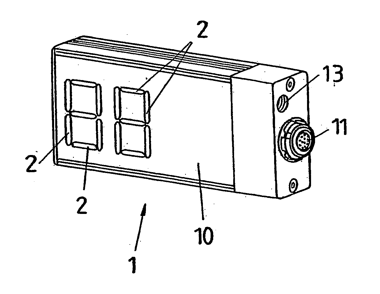
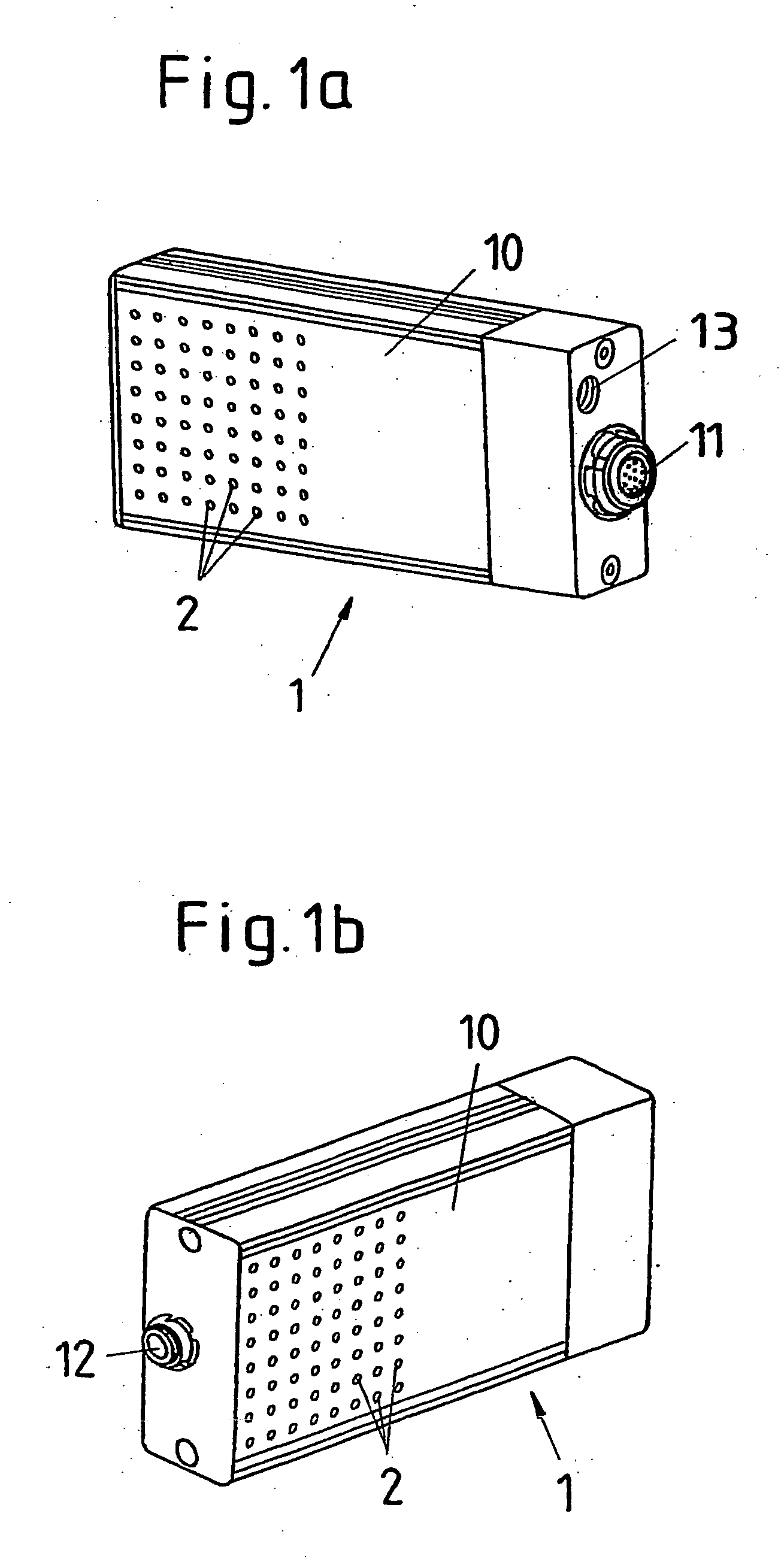
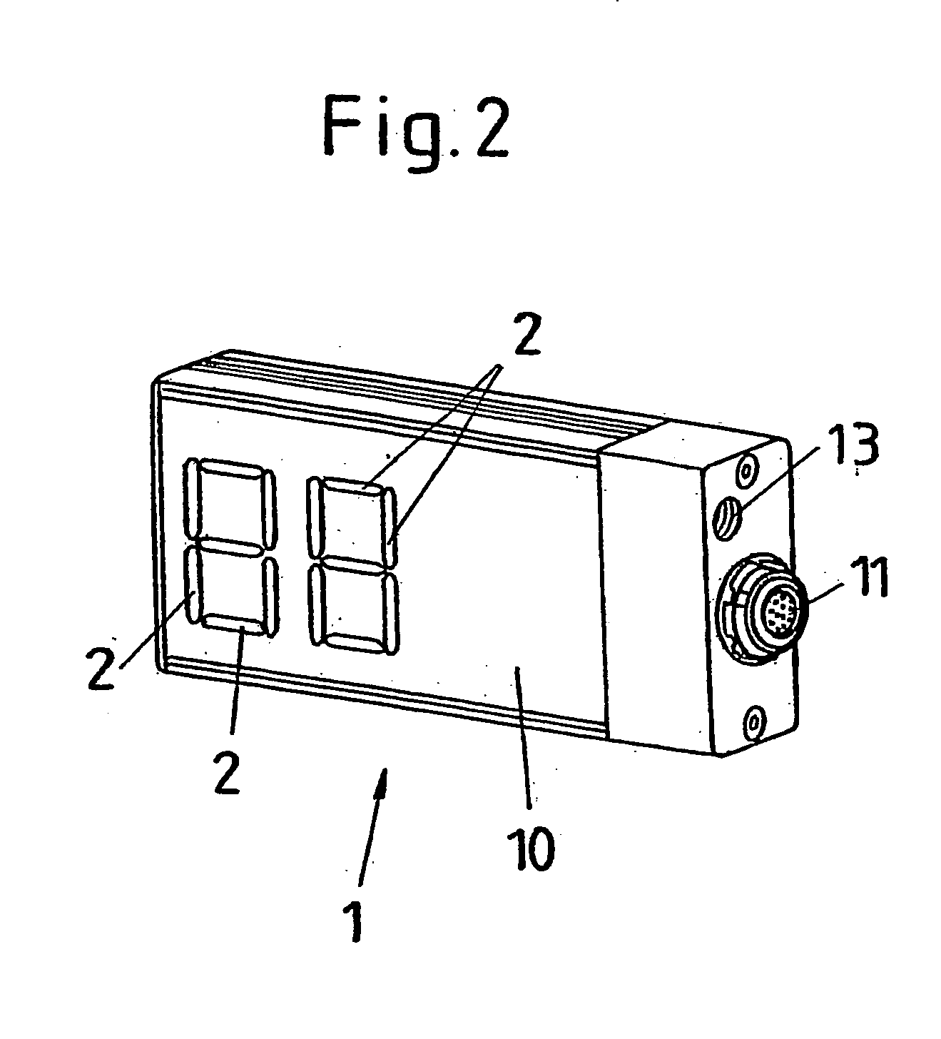
[0023]FIG. 1a shows a first exemplary embodiment of a synchronization device 1 having a square housing 10 in a side perspective view. On a side face of the housing is the control interface 11 for connection of the synchronization device 1 to the computer of a computer-controlled recording device (motion control) of a motion picture camera. This control interface 11 can be designed so that it can be connected to a CAN Bus system which is typical for motion-control systems.

[0024] On the same side face of the housing there is furthermore an internal thread 13 which enables the synchronization device 1 to be fixed onto an associated support element of the camera system.

[0025] On the surface of another side face are mounted as optical signaling elements 64 light elements 2 equidistant from each other in an 8×8 matrix. Each of the 64 light elements 2 comprises at least one light-emitting diode (LED). By means of a signaling device (not shown) mounted inside the housing 10 and comprising...


PUM


Abstract

The invention relates to a synchronization device (1) for providing an optical synchronization signal in computer-controlled picture recordings of a motion picture camera, comprising a signaling device for generating an optical synchronization signal, whereby the optical synchronization signal of the synchronization device (1) can be initiated by the computer that controls the picture recordings. The invention provides that the signaling device has a number of optical signaling elements (2). The signaling device having a number of optical signaling elements (2) enables, according to the combination possibilities provided by the number of optical signaling elements (2), the realization of at least one corresponding number of different optical signaling signals. With, for example, only two optical signaling elements, three different optical synchronization signals can already be formed (both signaling elements being active; only the first signaling element being active; only the second signaling element being active). A greater number of optical signaling elements enables the generation of a correspondingly large number of optical synchronization signals.

Description

CROSS-REFERENCE TO RELATED APPLICATION [0001] This application is a National Phase Patent Application of International Application Number PCT / DE2003 / 01115, filed on Mar. 28, 2003, which claims priority of German Patent Application Number 102 16 218.2, filed on Apr. 5, 2002.BACKGROUND OF THE INVENTION [0002] The invention relates to a synchronization device. [0003] A synchronization device of this kind serves to prepare an optical synchronization signal for computer-controlled picture recordings of a motion picture camera. For this, the synchronization device has a signaling device for generating an optical synchronization signal whereby the optical synchronization signal can be initiated by means of a computer which controls the picture recordings. [0004] In film productions computer-controlled camera moves are often carried out (motion control). In order to achieve a simpler synchronization of the individual takes of such computer-controlled motion control, a synchronization device...

Claims


Application Information

Patent Timeline
IPC IPC(8): H04N5/222H04N5/232
CPCH04N5/232H04N5/222H04N23/661
Inventor HAUBMANN, MICHAEL
Owner ARNOLD & RICHTER CINE TECHN & BETRIEBS
Why Eureka
Try Eureka