Method for Controlling a Multi-Zone Forced Air HVAC System To Reduce Energy Use

Active Publication Date: 2010-04-29
EMME E2MS
View PDF6 Cites 14 Cited by
  • Summary
  • Abstract
  • Description
  • Claims
  • Application Information

AI Technical Summary

Benefits of technology

[0019]The invention is an energy saving method for controlling multi-zone forced air HVAC systems where the minimum conditioned airflow produced by the HVAC equipment significantly exceeds the airflow capacity of many of the zones. When satisfying calls for conditioning from one or a few zones, excess

Problems solved by technology

One problem with simple zone control is that the amount of conditioned airflow needed depends on the number of zones calling for conditioning.
However, the extra ducting is expensive to install and requires space that may not be available.
This is usually not practical for retrofit.
In addition, when multiple zones call for conditioning, the airflow velocity to each zone is reduced, so the conditioned air may not mix properly with the unconditioned air in the zones.
A significant problem with using a bypass is the return air becomes heated or cooled.
This exceeds the recommend operating conditions for most residential HVAC equipment, voiding the manufacturer's warranty.
When in cooling mode, excessive bypass can reduce the return air temperature sufficiently

Method used


Image

  • Method for Controlling a Multi-Zone Forced Air HVAC System To Reduce Energy Use
  • Method for Controlling a Multi-Zone Forced Air HVAC System To Reduce Energy Use
  • Method for Controlling a Multi-Zone Forced Air HVAC System To Reduce Energy Use

Examples


Embodiment Construction

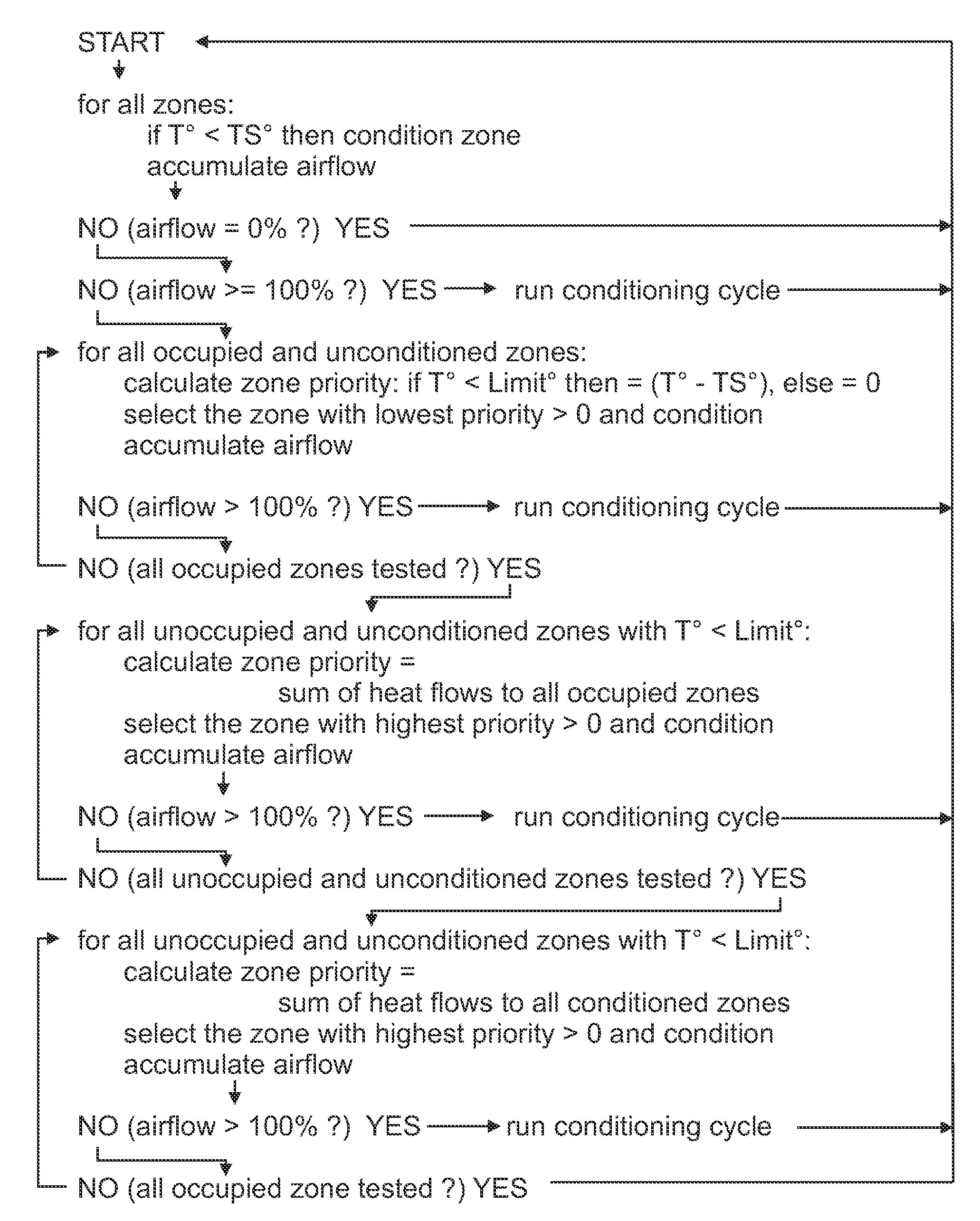
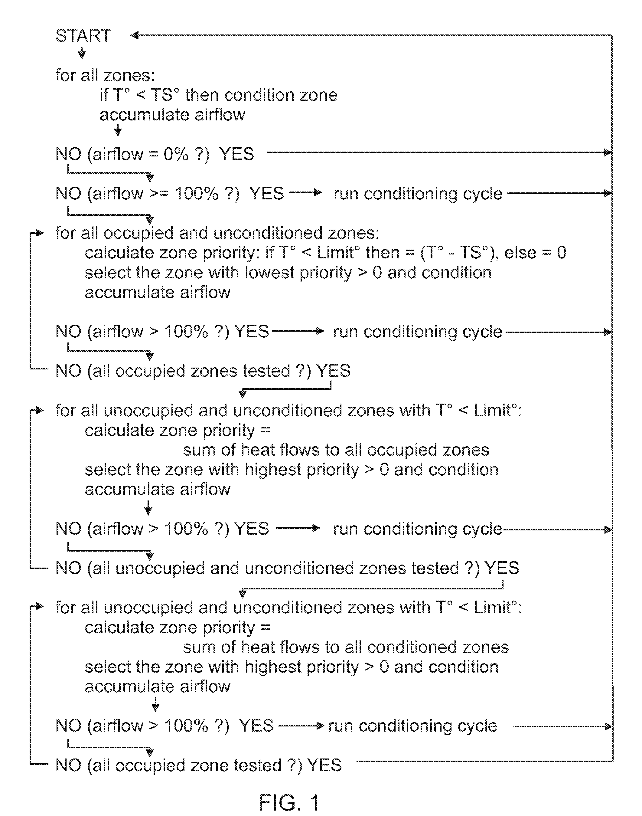
[0029]FIG. 1 is a logic flow diagram of the improved method for selecting non-calling zones to receive excess conditioned airflow. The method makes decisions based on the occupancy of each zone. Each zone is either occupied or unoccupied so the total of the occupied zones and unoccupied zones equals the total number of zones in the HVAC system.

[0030]The set temperature of a zone can be used to determine its occupancy. For example if the heating set temperature is less than a preset heating threshold such as 55°, it is reasonable to assume the zone is unoccupied. Likewise if the cooling set temperature is greater than a preset cooling temperature such as 900, it is reasonable to assume the zone is unoccupied.

[0031]Other ways to determine occupancy can be used with the improved method. For example the temperature sensor for each zone can have a switch or button for communicating the occupied or unoccupied state to the zone control system. The occupant is responsible for setting the st...


PUM


Abstract

In a multi-zone control system for central forced air HVAC systems where the minimum conditioned airflow produced by the HVAC equipment significantly exceeds the airflow capacity to many of the zones, the invention is an energy saving method for choosing non-calling zones to receive excess airflow in. When satisfying calls for conditioning from one or a few zones, excess conditioned airflow is directed to non-calling zones. The method chooses occupied non-calling zones using a priority that provides comfort, and chooses unoccupied non-calling zones using a different priority that provides energy savings. Limits are provided for each zone to prevent excessive over conditioning in non-calling zones.

Description

BACKGROUND OF THE INVENTION[0001]1. Technical Field of the Invention[0002]This invention relates generally to multi-zone forced-air HVAC systems, and specifically to control methods for reducing conditioning and energy consumption.[0003]2. Background Art[0004]Most zone control systems for residential forced-air HVAC systems have a small number of zones in combination with HVAC equipment that has fixed capacity or variable capacity over a limited range or discrete steps of capacity. Simple zone control systems have a convention thermostat for each zone. Each zone has and airflow control damper that is opened or closed by signals from the thermostat for that zone. The calls for conditioning from each thermostat are combined using a logical OR function. The conditioning equipment runs when one or more thermostats make a call for conditioning. When a thermostat calls for conditioning, the damper for that zone is open. When the zone thermostat is not calling for conditioning, the damper ...

Claims


Application Information

Patent Timeline
IPC IPC(8): F24F7/00
CPCF24F3/044F24F11/0034Y02B30/767F24F2011/0075F24F11/006F24F11/30F24F2120/10F24F11/62F24F11/46
Inventor ALLES, HAROLD GENE
Owner EMME E2MS
Why Eureka
Try Eureka