Apparatus and method for aligning an image sensor

Inactive Publication Date: 2010-04-29
EXCELIS INC
View PDF19 Cites 33 Cited by
  • Summary
  • Abstract
  • Description
  • Claims
  • Application Information

AI Technical Summary

Problems solved by technology

Incorporating a filmed MCP into an image intensifier tube has generated a new set of challenges.

Method used


Image

  • Apparatus and method for aligning an image sensor
  • Apparatus and method for aligning an image sensor
  • Apparatus and method for aligning an image sensor

Examples


Embodiment Construction

[0020]The invention is best understood from the following detailed description when read in connection with the accompanying drawing figures, which show an exemplary embodiment of the invention selected for illustrative purposes. Such figures are intended to be illustrative rather than limiting and are included herewith to facilitate the explanation of the present invention. The invention is not intended to be limited to the details shown. Although the invention is illustrated and described herein with reference to a specific embodiment, various modifications may be made in the details within the scope and range of equivalents of the claims and without departing from the invention.

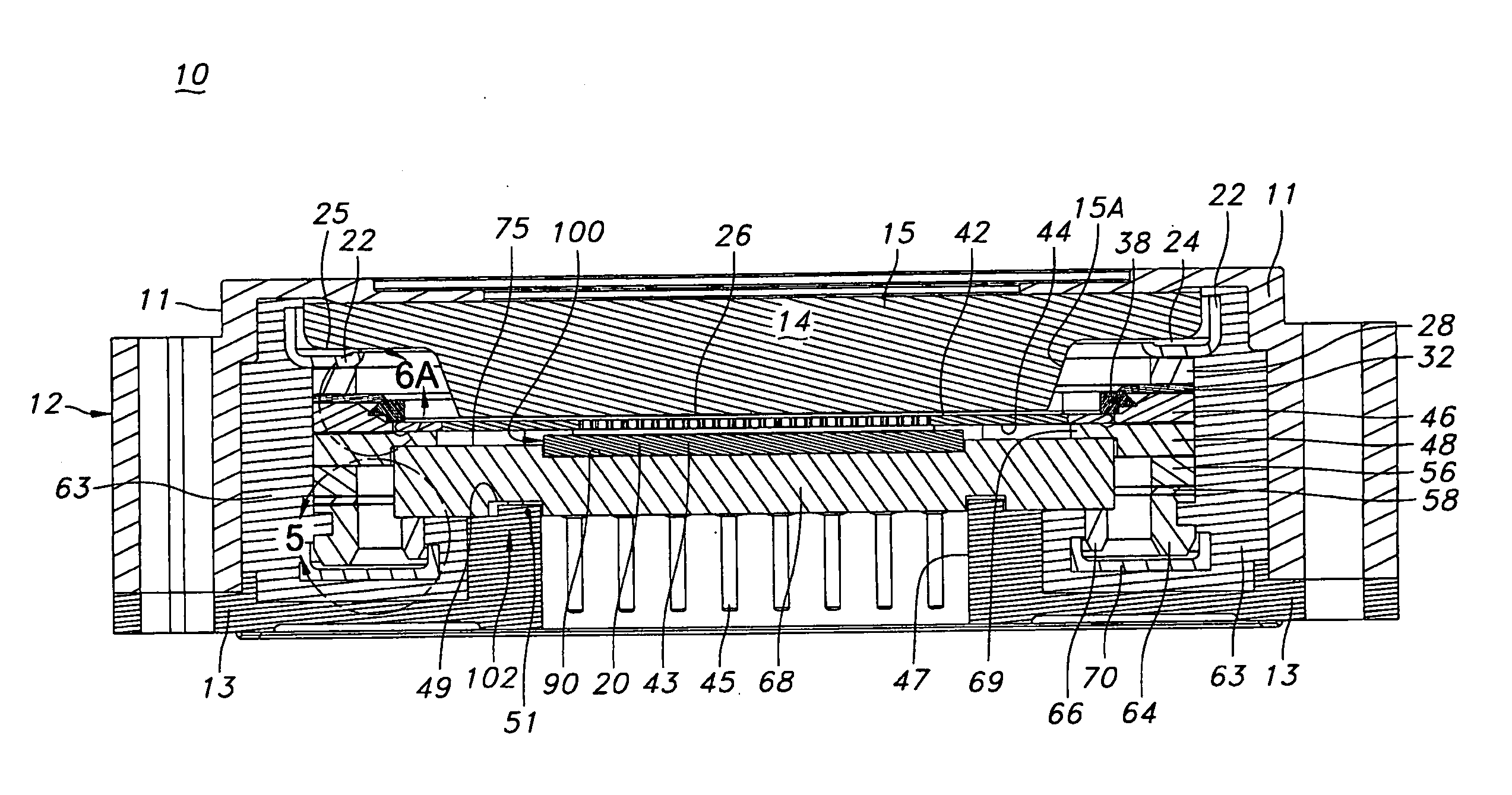
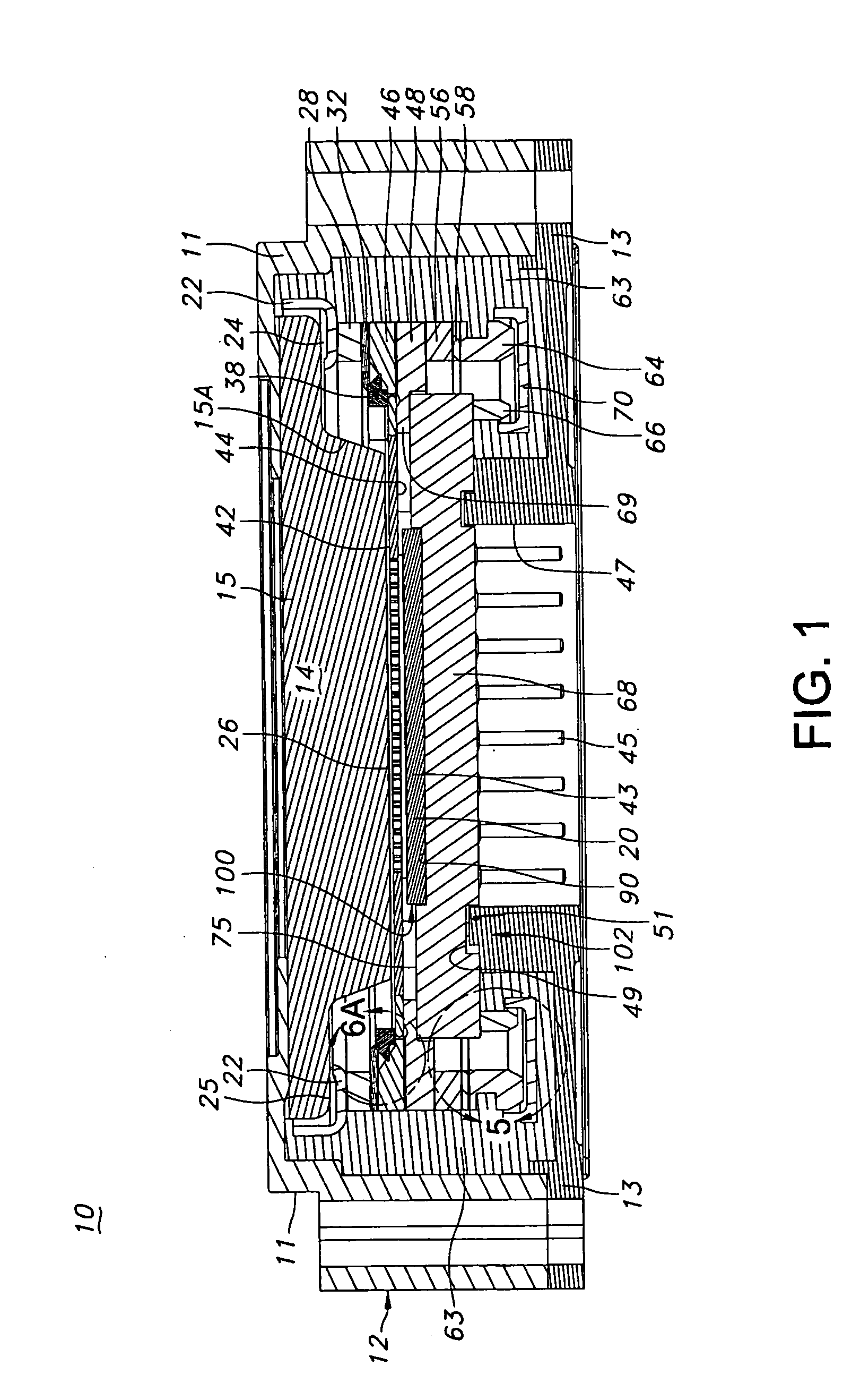
[0021]FIG. 1 depicts a cross-sectional view of an image intensifier tube 10 (hereinafter tube 10) according to one exemplary embodiment of the invention. Tube 10 includes an evacuated housing 12 including a front cover 11 that is mounted to a rear cover 13. Within housing 12, there is positioned photocatho...


PUM


Abstract

An imaging device and a method for aligning an image sensor within the imaging device are disclosed. The imaging device comprises a housing and an image sensor assembly including a header and an image sensor mounted to the header. The header of the image sensor assembly is coupled to the housing. Means for aligning the image sensor with respect to the header are provided. Means for aligning the header with respect to the housing of the imaging device are also provided. A distance separating the image sensor alignment means and the header alignment means is pre-determined such that a distance between the image sensor and the housing of the imaging device is pre-determined.

Description

BACKGROUND OF THE INVENTION[0001]Image intensifier devices are employed in night visions systems to convert a dark environment to a bright environment that is perceivable by a viewer. Night vision systems have industrial, commercial and military applications. The image intensifier device collects tiny amounts of light in a dark environment, including the lower portion of the infrared light spectrum, that are present in the environment but imperceptible to the human eye. The device amplifies the light so that the human eye can perceive the image. The light output from the image intensifier device can either be supplied to a camera, external monitor or directly to the eyes of a viewer.[0002]Image intensifier devices generally include three basic components mounted within an evacuated housing, namely, a photocathode (commonly called a cathode), a microchannel plate (MCP) and an anode. The photocathode is a photosensitive plate capable of releasing electrons when it is illuminated by li...

Claims


Application Information

Patent Timeline
Patent Type & Authority Applications(United States)
IPC IPC(8): H01L31/0203H01L31/02
CPCH01J31/26
Inventor GARRIS, WILLIAM ERIC
Owner EXCELIS INC
Why Eureka
Try Eureka