Tube fitting

a technology for fittings and tubes, applied in the direction of hose connections, fluid pressure sealed joints, sleeves/socket joints, etc., can solve the problems of difficult operation of putting the open tubular body therein with pressure, and difficulty in easy attachment and detach operations, etc., to achieve the effect of easy attachment and detachment of tubes

Inactive Publication Date: 2010-04-29
YUGEN KAISHA HAMA INT
View PDF20 Cites 5 Cited by
  • Summary
  • Abstract
  • Description
  • Claims
  • Application Information

AI Technical Summary

Benefits of technology

[0011]With the above configuration, it is made possible to provide a tube fitting capable of easily attach and detach a tube by one ha

Problems solved by technology

However, the conventional tube fitting as shown in the Patent reference 1 has a problem in that, when a tube is pulled out from the main body of the fitting, it is necessary that the open tubular body is put therein with pressure and the tube is pulled out in a pulling and removing direction and, therefore, manipulation of the fitting and tube with both hands is required, which makes it difficult to perform easy

Method used


Image

  • Tube fitting
  • Tube fitting
  • Tube fitting

Examples


embodiment

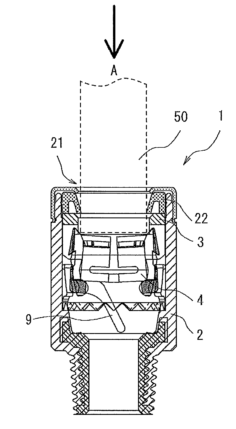
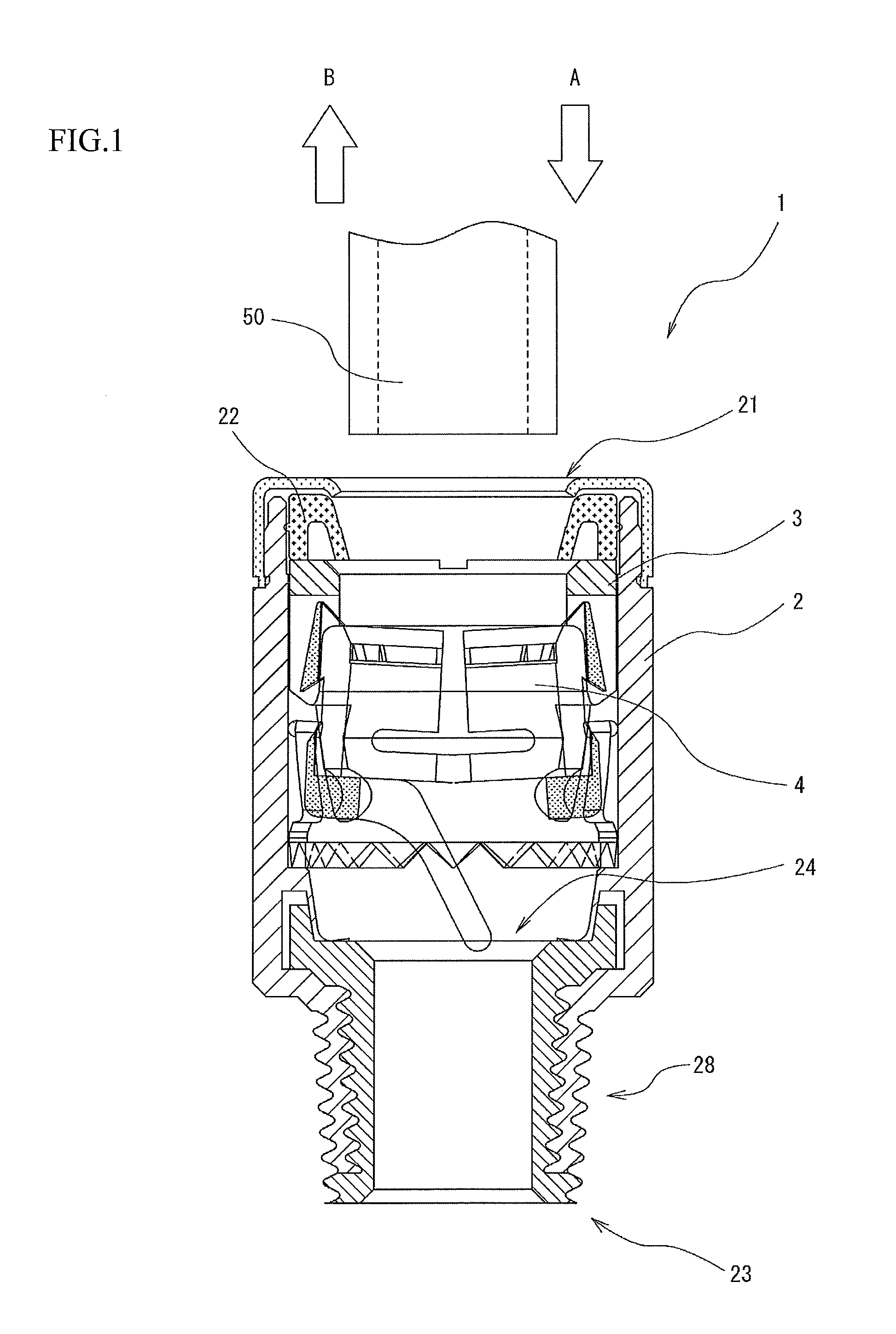
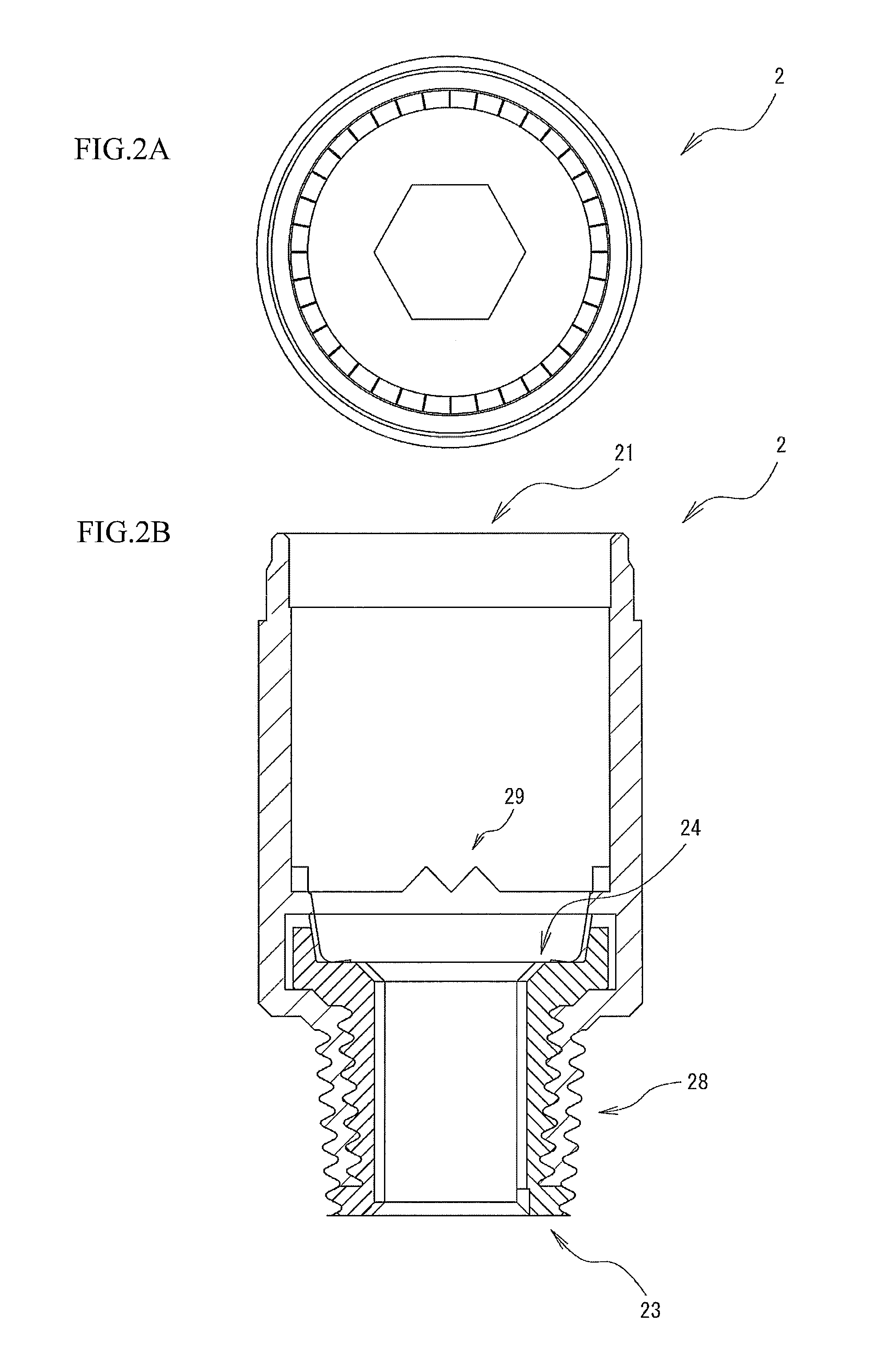
[0023]As shown in FIG. 1, the tube fitting 1 of the embodiment of the present invention is formed so as to be tubular-shaped and to have the main body 2 into which a tube 50 is inserted from an opening part 21 on one end part in an axial direction. The other end part 23 of the main body 2 is connected, by a connection screw 28, to a connection hole (not shown) of an external fluid apparatus (not shown) from or to which a fluid flows.

[0024]Into the main body 2 is internally fitted the sleeve 3 having a tubular shape (see FIGS. 3A, 3B, and 3C) so that the axial direction of the sleeve 3 coincides with the axial direction of the main body 2 and so that the sleeve 3 is fixed in the main body 2. Also, into the sleeve 3 is internally fitted a locking member 4 (see FIGS. 4A, 4B, and 4C) made up of a ring part 5 having a ring shape and a plurality of extended parts 6 each coming out in a state of being extended from the ring part 5 in an axial direction. The locking member 4 is configured s...


PUM


Abstract

A tube fitting is provided which is capable of easily attaching and detaching a tube by one hand manipulation and of more improving attachability and detachability and setting pressure contact force to be higher. The tube fitting including a tubular main body, a sleeve being tubular-shaped and being fixed in the main body with axial lines of the main body and the sleeve coincided with each other, a locking member having a ring part and a plurality of extended parts extending from the ring part toward an axial direction and being mounted in the sleeve in a state where axial lines of the ring part and the sleeve are coincided with each other and being movable in the sleeve in an axial direction and in a circumferential direction.

Description

BACKGROUND OF THE INVENTION[0001]1. Field of the Invention[0002]The present invention relates to a tube fitting and more particularly to the tube fitting having a main body so formed as to be tubular-shaped and so configured as to lock a tube inserted from an opening part on one end side of the main body and to be able to hold the tube.[0003]2. Description of the Related Art[0004]One example of a conventional tube fitting is disclosed in Patent reference 1 (Japanese Patent Application Laid-open No. 2002-106772). The conventional tube fitting disclosed in the Patent reference 1 has a pipe-shaped main body of a fitting, a guiding tubular body one end of which is inserted into the fitting main body with pressure and is fixed in the fitting main body, a stopper fixed in the guiding tubular body in a state where one end of a guiding case is caulked, an open tubular body held by one end of the guiding tubular body so as to be freely moved in an axial direction, a seal ring, and a locking ...

Claims


Application Information

Patent Timeline
IPC IPC(8): F16L37/00
CPCF16L17/035F16L37/0925F16L33/227F16L37/12F16L37/084F16L37/08F16L21/08
Inventor HAMA, TOMIOHAMAUE, YUJI
Owner YUGEN KAISHA HAMA INT
Why Eureka
Try Eureka