Linear drive having shock compensation

a linear drive and shock compensation technology, applied in piezoelectric/electrostriction/magnetostriction machines, dynamo-electric machines, electrical apparatus, etc., can solve the problems of actuator slippage along the drive unit, actuator damage to the thread, and the possibility of manipulating the movement of the actuator

Active Publication Date: 2010-04-29
MINEBEAMITSUMI INC
View PDF7 Cites 11 Cited by
  • Summary
  • Abstract
  • Description
  • Claims
  • Application Information

AI Technical Summary

Benefits of technology

[0018]Whereas the known friction-coupled linear drives, such as piezoelectric linear drives, can absorb a force of impact of up to a maximum of 100 G through their friction coupling, thanks to the invention, reliable blocking of the sliding element for shock loads of over 500 G, and even up to 1500 G and beyond can be achieved.

Problems solved by technology

Directly coupled linear drives have the disadvantage that it is possible to manipulate the movement of the actuator by applying an external force.
In particular, when exposed to a shock or impact load or any other mechanical stress, such as vibration that is applied to the linear drive from an external source, the actuator may slip along the drive unit because the directly coupled linear drive has only a limited self-restraining effect.
If the thread pitch, for example, is low, an external force, such as a shock load, immediately results in damage to the thread.
If the pitch of the thread is high, a shock load results in the actuator slipping through, similar to directly coupled linear drives.
If used, for example, for actuating a lock cylinder, the fact that the actuator could be manipulated by a simple external shock load or an externally applied vibration would of course be highly disadvantageous.

Method used


Image

  • Linear drive having shock compensation
  • Linear drive having shock compensation
  • Linear drive having shock compensation

Examples


Embodiment Construction

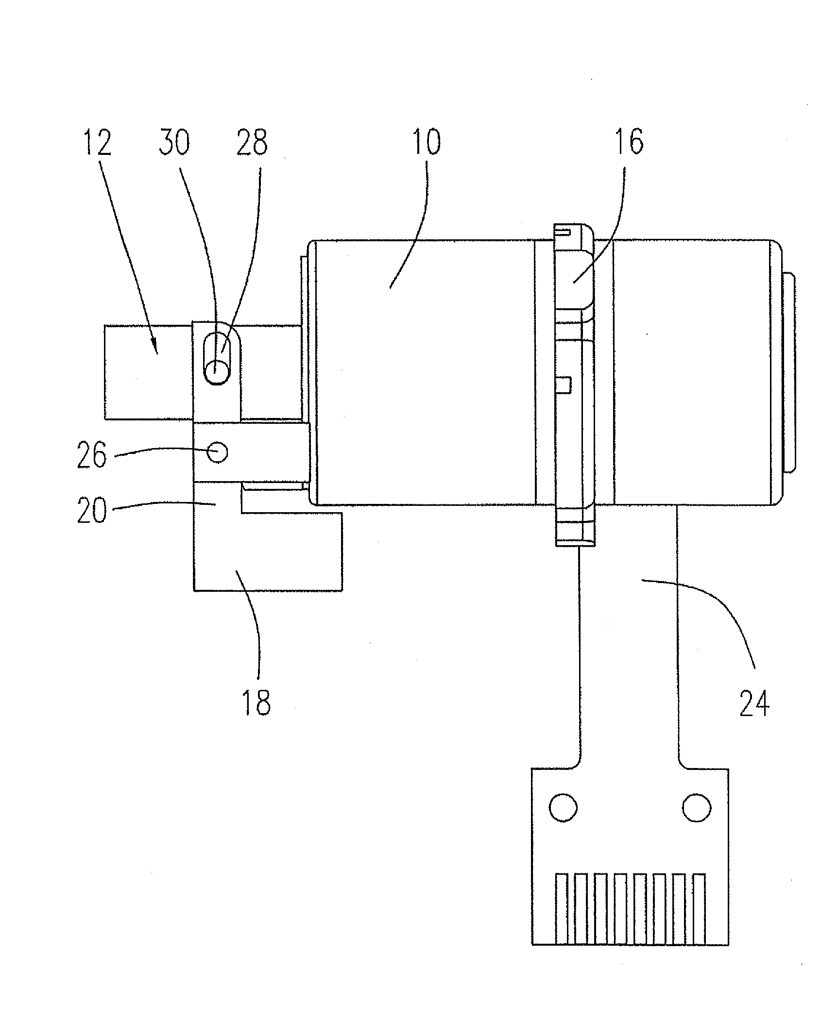
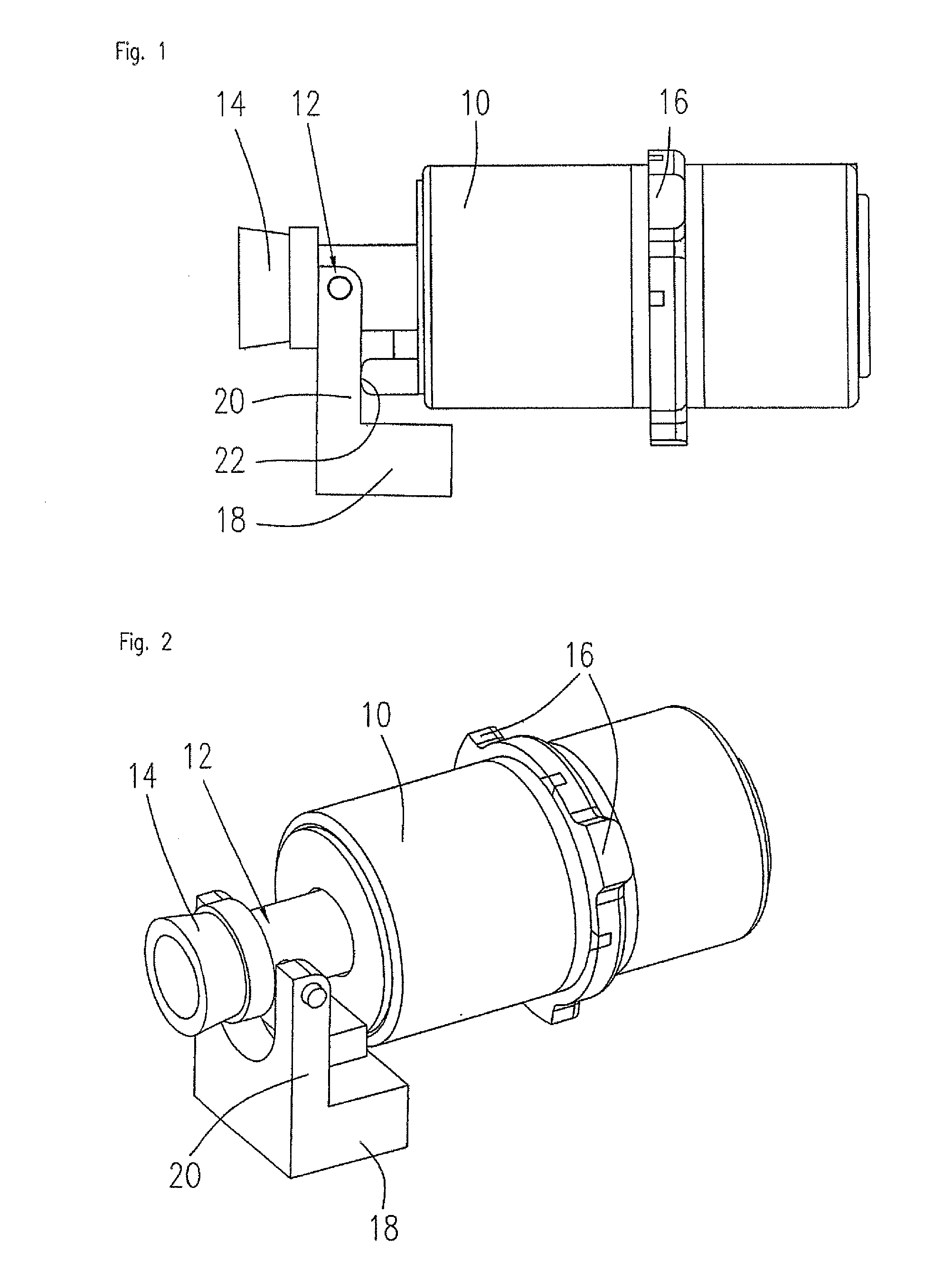
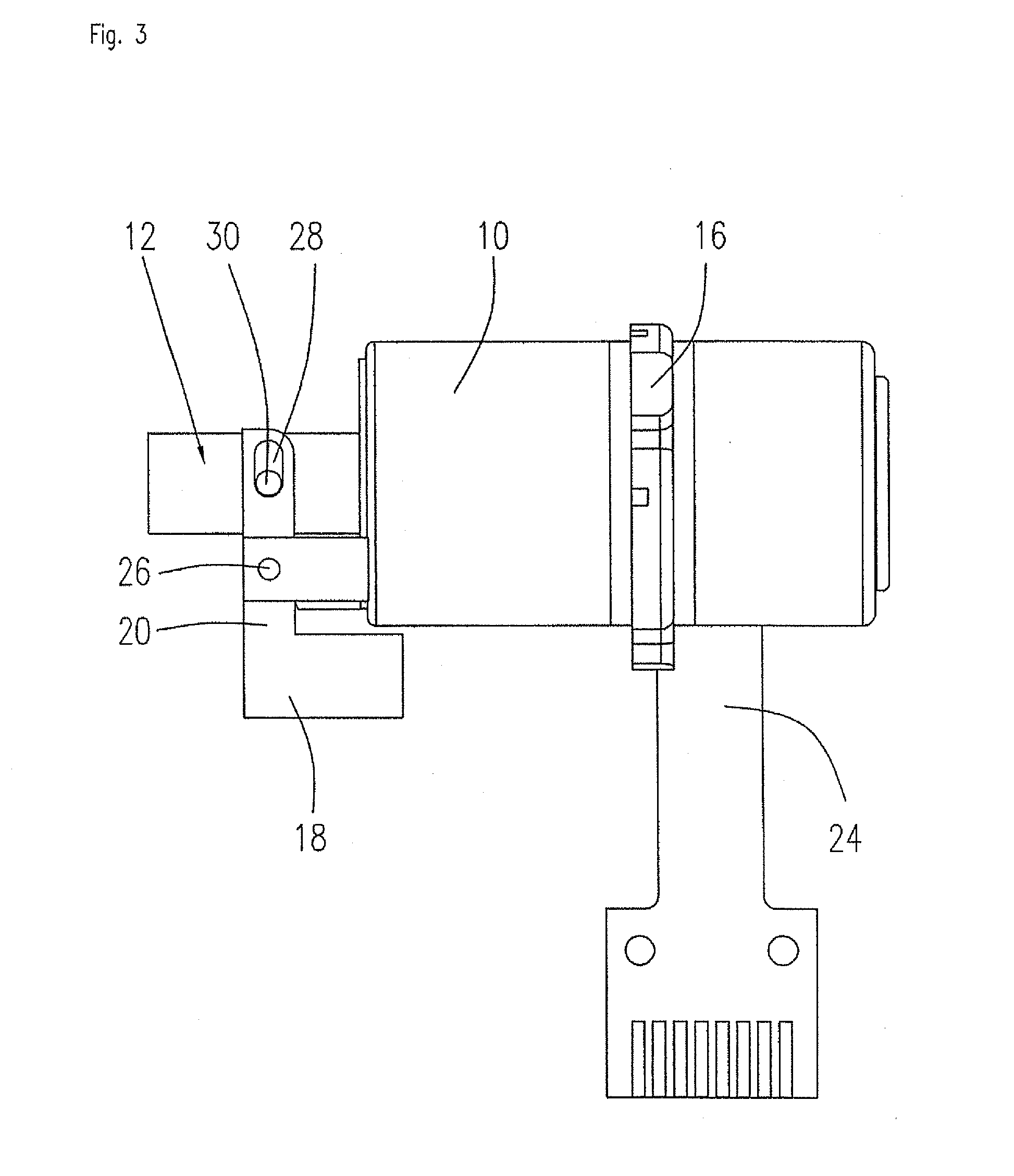
[0040]FIGS. 1 and 2 show a side view as well as an isometric view of the friction-coupled linear drive according to one embodiment of the invention. In FIGS. 1 and 2, first a drive housing 10 and a sliding element of the linear drive, more specifically an actuator 12 connected to the sliding element, are illustrated. A blocking pin 14 is mounted on the actuator 12, the blocking pin 14 being used in the locking application mentioned at the outset to block the lock cylinder. Damping elements taking the form of elastomer members 16 are mounted on the outside circumference of the drive housing 10. The elastomer members which in the illustrated embodiment take the approximate shape of cuboid blocks may be directly molded or bonded to the housing 10, or connected in some other manner to the drive housing 10. Instead of using the illustrated elastomer members, damping strips may be mounted in an axial direction or in a circumferential direction on the outside surface of the drive housing 1...


PUM


Abstract

A directly coupled linear drive having a drive unit and a sliding element that are disposed in a frame, the sliding element, actuated by the drive unit, being capable of effecting a movement in a direction of translation with respect to the frame and having a blocking device for blocking the sliding element in the frame in the event of a shock load to the sliding element, the blocking device having a body coupled to the sliding element that absorbs the shock load and is disposed such that the shock load of the body counteracts the shock load of the sliding element.

Description

FIELD OF THE INVENTION[0001]The invention relates to linear motors in general and more specifically to directly coupled linear drives, such as a friction-coupled linear drive or a magnetic drive. Examples of friction-coupled linear drives, for which the invention finds application, include electromechanical linear motors having a drive element that is made of an electrostrictive or magnetostrictive material. Also known are polymer actuators that are made of a combination of polymer and metallic materials and that allow an electrically controllable movement of a polymer body.BACKGROUND OF THE INVENTION[0002]WO 2004 / 001867 describes an example of a piezoelectric motor that provides a linear drive for an actuator. The motor uses a piezoelectric drive element that operates at high speed and with high precision. The piezoelectric motor described in WO 2004 / 001867 A1 comprises a stator that consists of two series-connected bending sections and a power transmission element which is mounted...

Claims


Application Information

Patent Timeline
Patent Type & Authority Applications(United States)
IPC IPC(8): H02K41/02
CPCH02N2/0015H02N2/04H02N2/026
Inventor TRIETZ, THOMASBLOCHER, BERNHARDSCHMID, GUIDOSCHNEIDER, HELMUTWILLMER, MARTINSCHWAMBERGER, STEFANKREIENSEN, ULLRICHPOPOV, VLADIMIR V.
Owner MINEBEAMITSUMI INC
Why Eureka
Try Eureka