Engine generator

Inactive Publication Date: 2003-04-17
HONDA MOTOR CO LTD
View PDF9 Cites 13 Cited by
  • Summary
  • Abstract
  • Description
  • Claims
  • Application Information

AI Technical Summary

Problems solved by technology

Moreover, in the arrangement disclosed in Japanese Patent Application Laid-open No. 11-62607, the structure for forming a passage for the cooling air is complicated, and during maintenance it i

Method used


Image

  • Engine generator
  • Engine generator
  • Engine generator

Examples


Embodiment Construction

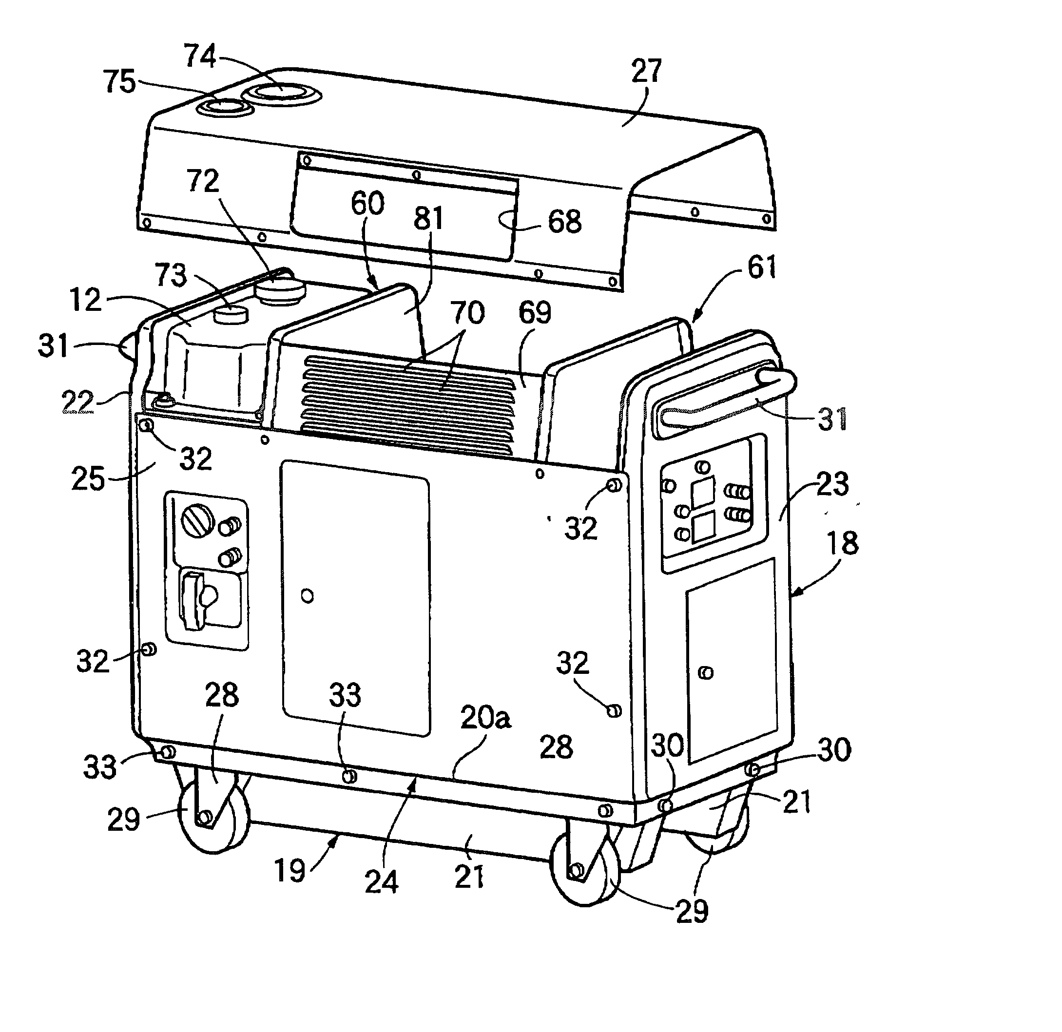
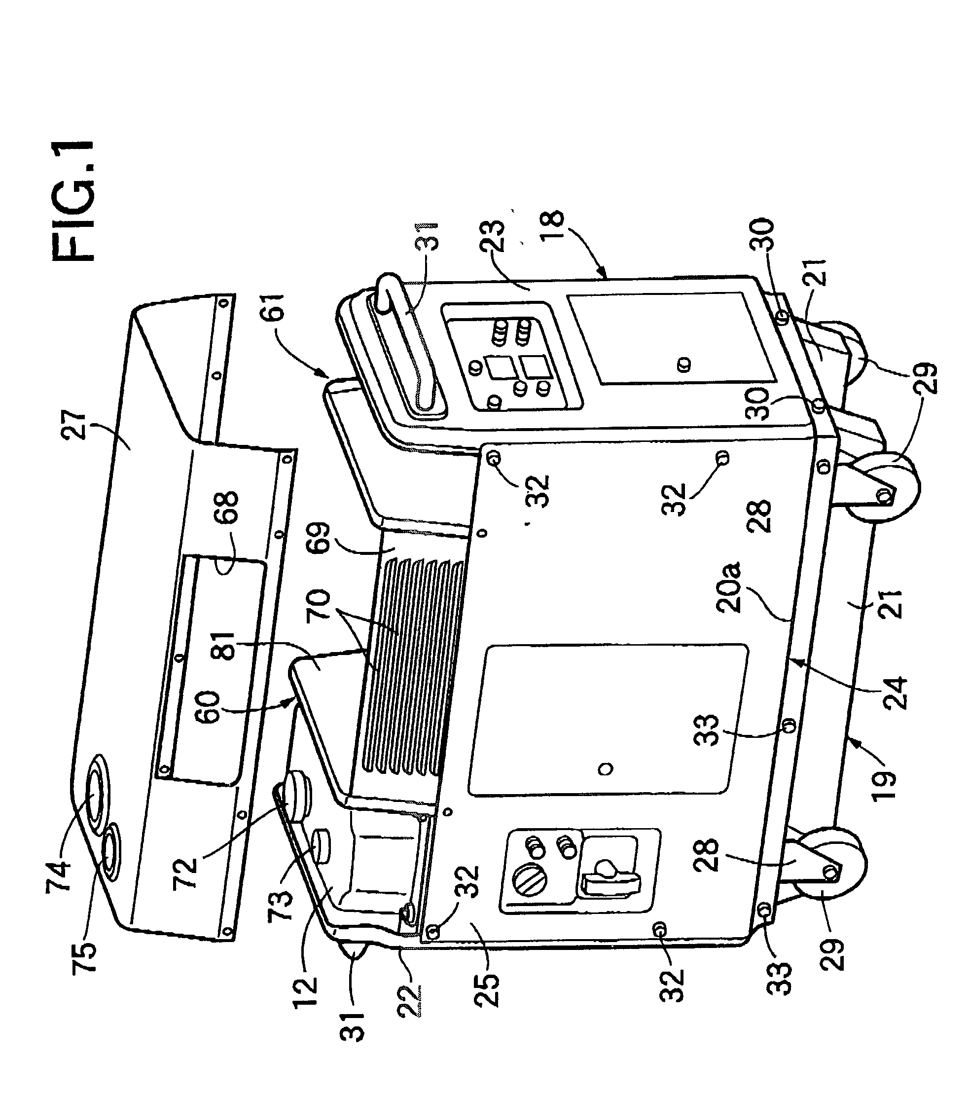
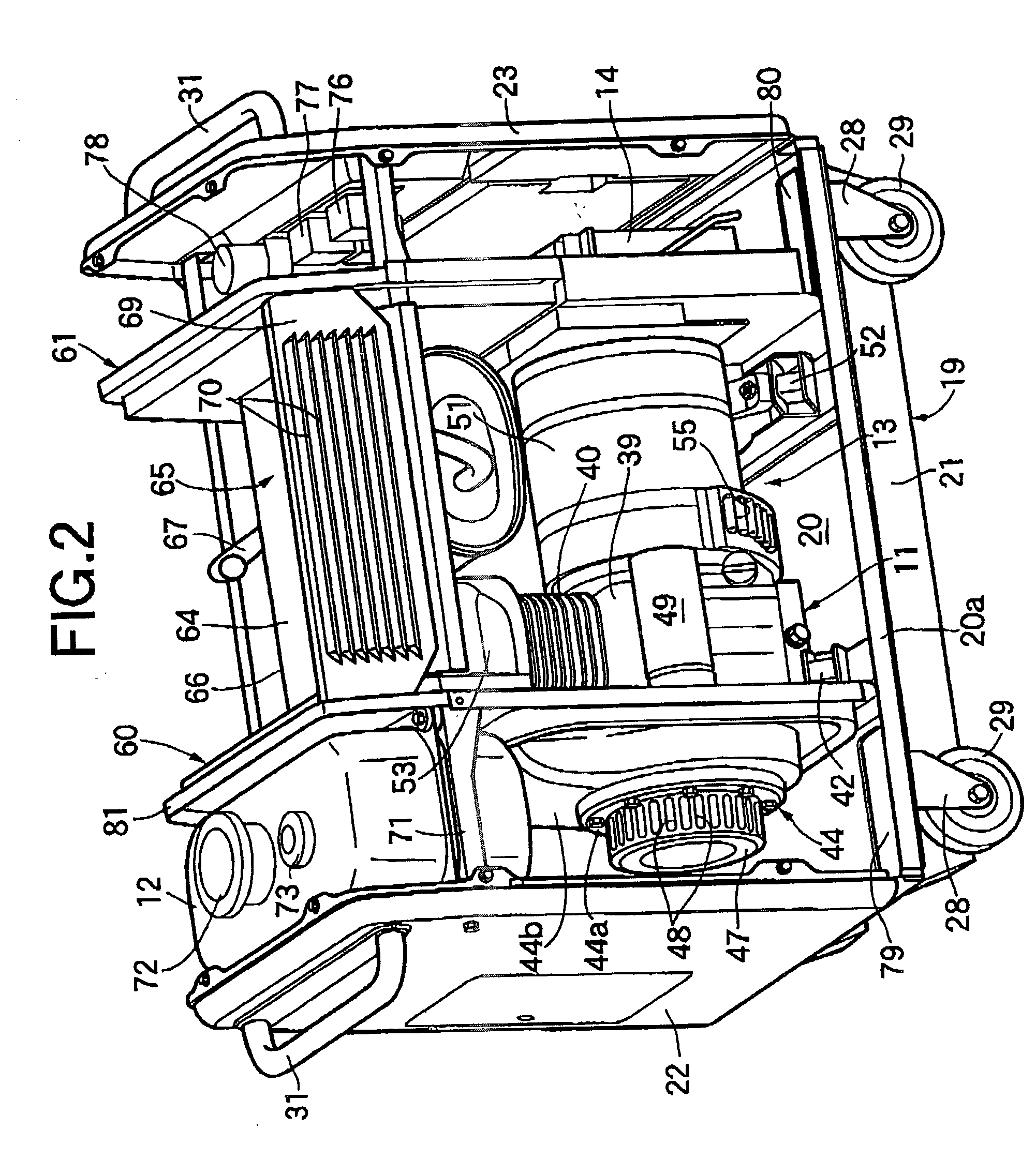
[0025] Referring to FIGS. 1 to 5, an engine generator includes a soundproofing case 18 housing an engine 11, a fuel tank 12, a generator 13 driven by the engine 11, a battery 14, an air cleaner 15, a carburetor 16 and an exhaust muffler 17 connected to the engine 11. The soundproofing case 18 is formed from a substantially rectangular base frame 19, first and second side plates 22, 23 standing on longitudinally opposite ends of the base frame 19, and a cover part 24 covering the base frame 19 between the two side plates 22, 23.

[0026] The base frame 19 is formed from a substantially rectangular base plate 20 and a pair of reinforcing frames 21 fixed to the lower face of the base frame 20. The reinforcing frames 21 are fixed at positions spaced in the width direction of the base plate 20 and extending in the longitudinal direction of the base plate 20. Each reinforcing frame 21 is formed from substantially U-shaped steel so as to define, between the frame 21 and the lower face of the ...


PUM


Abstract

An engine generator including a soundproofing case that houses an engine and a generator therein. The engine includes an engine-side cooling fan and an engine-side inlet. The generator includes a generator-side cooling fan and a generator-side inlet. The engine generator further includes an engine-side partition and a generator-side partition fixedly disposed within the soundproofing case to define a chamber to be cooled that houses sections of the engine and the generator that are to be cooled, an engine-side air intake chamber that the engine-side inlet faces, and a generator-side air intake chamber that the generator-side inlet faces. The soundproofing case includes a cover part whose inside face is in intimate contact with the outer peripheries of the engine-side and generator-side partitions and has an exhaust vent in a part corresponding to the chamber to be cooled.

Description

[0001] 1. Field of the Invention[0002] The present invention relates to an engine generator. In particular, the present invention relates to an improvement of an engine generator in which an engine and a generator are housed in a soundproofing case. The engine includes a crankshaft, an engine-side cooling fan fixed to the crankshaft, and an engine-side inlet provided at one end, in the axial direction, of the crankshaft for guiding cooling air to the engine-side cooling fan. The generator includes a rotating shaft connected at one end to the other end of the crankshaft, a generator-side cooling fan fixed to the rotating shaft, and a generator-side inlet provided at the other end, in the axial direction, of the rotating shaft for guiding cooling air to the generator-side cooling fan.[0003] 2. Description of the Related Art[0004] Engine-driven generators are typically used as a power source for work performed outdoors such as, for example, on construction sites. Furthermore, many gene...

Claims


Application Information

Patent Timeline
IPC IPC(8): F02B63/04F02B75/16F02B77/13H02K5/20H02K7/18H02K9/06
CPCF02B63/04F02B63/047F02B75/16H02K9/06F02B2063/045H02K5/20H02K7/1815F02B77/13H02K5/207
Inventor SUGIMOTO, YASUOTANAKA, YOSHIO
Owner HONDA MOTOR CO LTD
Why Eureka
Try Eureka