
Cooling structure for inverter and capacitor accommodated integrally with motor in housing of motor, motor unit with cooling structure, and housing

a technology of inverter and capacitor, which is applied in the direction of lighting and heating apparatus, magnetic circuit rotating parts, and shape/form/construction of magnetic circuits, etc. it can solve the problems of undesirable transfer of heat from the motor to the smoothing capacitor via the housing, and the motor may not absorb heat from the coolant, so as to achieve the effect of dissipating hea

Active Publication Date: 2012-04-03
TOYOTA JIDOSHA KK +1
View PDF23 Cites 12 Cited by
  • Summary
  • Abstract
  • Description
  • Claims
  • Application Information

AI Technical Summary

Benefits of technology

This solution effectively blocks heat transfer from the motor to the inverter and capacitor, ensuring efficient cooling and preventing component degradation by utilizing a coolant flow path that directs heat away from sensitive components, enhancing the reliability and performance of the motor unit.

Problems solved by technology

However, the inverter-integrated motor for a vehicle of Japanese Patent Laying-Open No. 2003-324903 is absolutely silent about the specific location of the path of the low-pressure coolant gas.
Therefore, in the case where a channel for the coolant is not provided at the housing between the motor and the power switching element, the heat from the motor may not be absorbed by the coolant and be undesirably transferred to the power switching element via the housing.
Similarly, in the case where a channel for the coolant is not provided at the housing between the motor and the smoothing capacitor, the heat from the motor may be undesirably transferred to the smoothing capacitor via the housing.

Method used


Image

  • Cooling structure for inverter and capacitor accommodated integrally with motor in housing of motor, motor unit with cooling structure, and housing
  • Cooling structure for inverter and capacitor accommodated integrally with motor in housing of motor, motor unit with cooling structure, and housing
  • Cooling structure for inverter and capacitor accommodated integrally with motor in housing of motor, motor unit with cooling structure, and housing

Examples


Embodiment Construction

[0029]Embodiments of the present invention will be described hereinafter with reference to the drawings. In the following, the same components have the same reference characters allotted. Their designation and function are also identical. Therefore, detailed description thereof will not be repeated.

[0030]

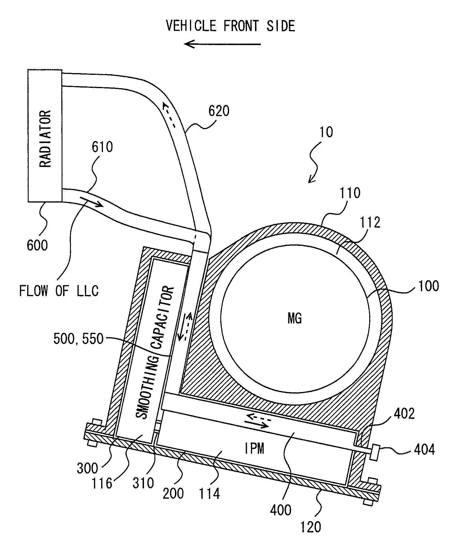
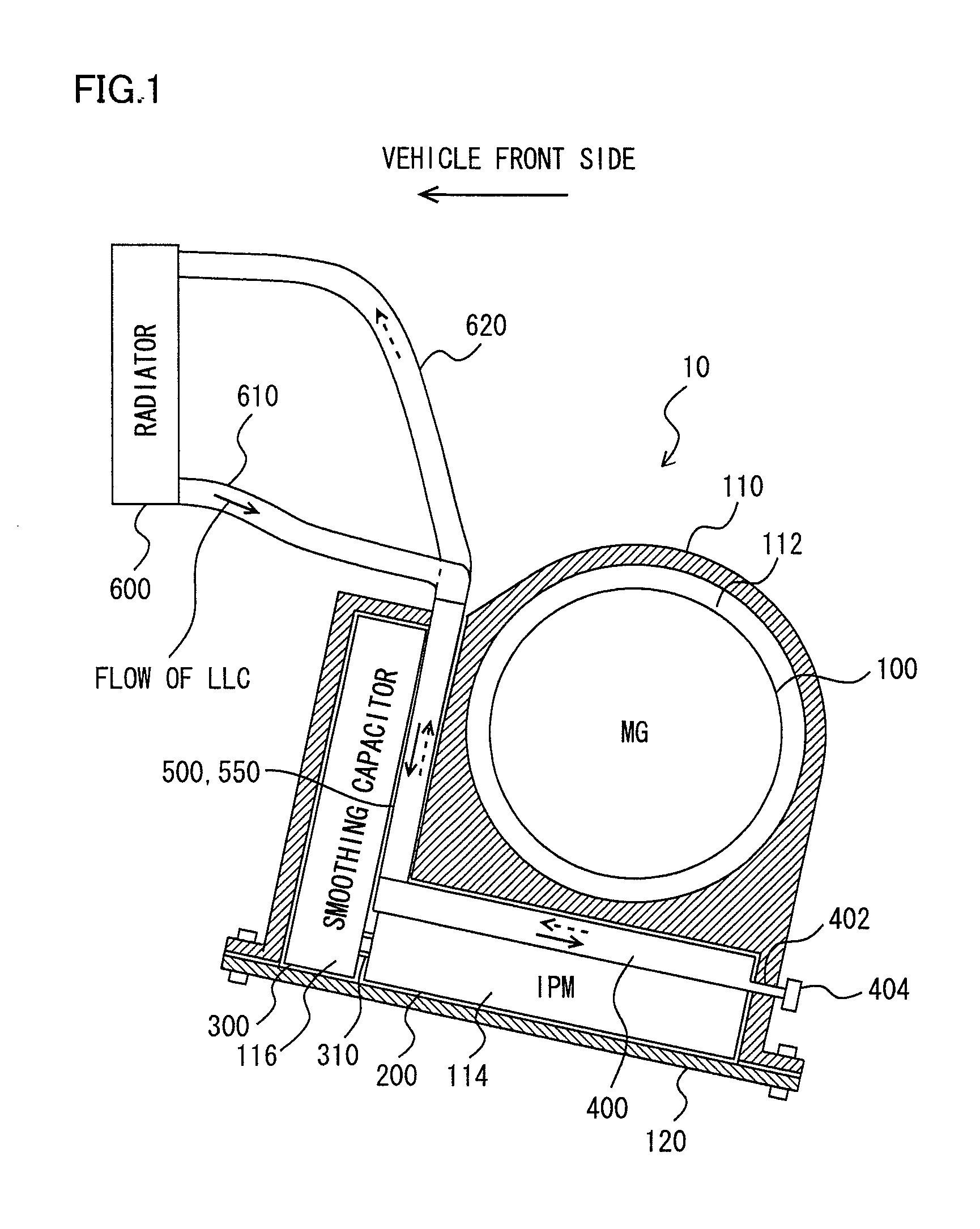
[0031]A configuration of a vehicle incorporating a motor unit 10 with a cooling structure according to the present embodiment will be described with reference to FIG. 1. Although the present embodiment will be described based on an electric car running only by the driving force from motor unit 10 as the vehicle, the vehicle mounted with a cooling structure for a capacitor according to the present invention is not limited to an electric car, and may be applied to a hybrid vehicle. Further, the present invention is not particularly limited to motor unit 10 for driving a vehicle.

[0032]The vehicle includes a motor unit 10 providing a driving force by the power supplied from a battery (n...


PUM


Abstract

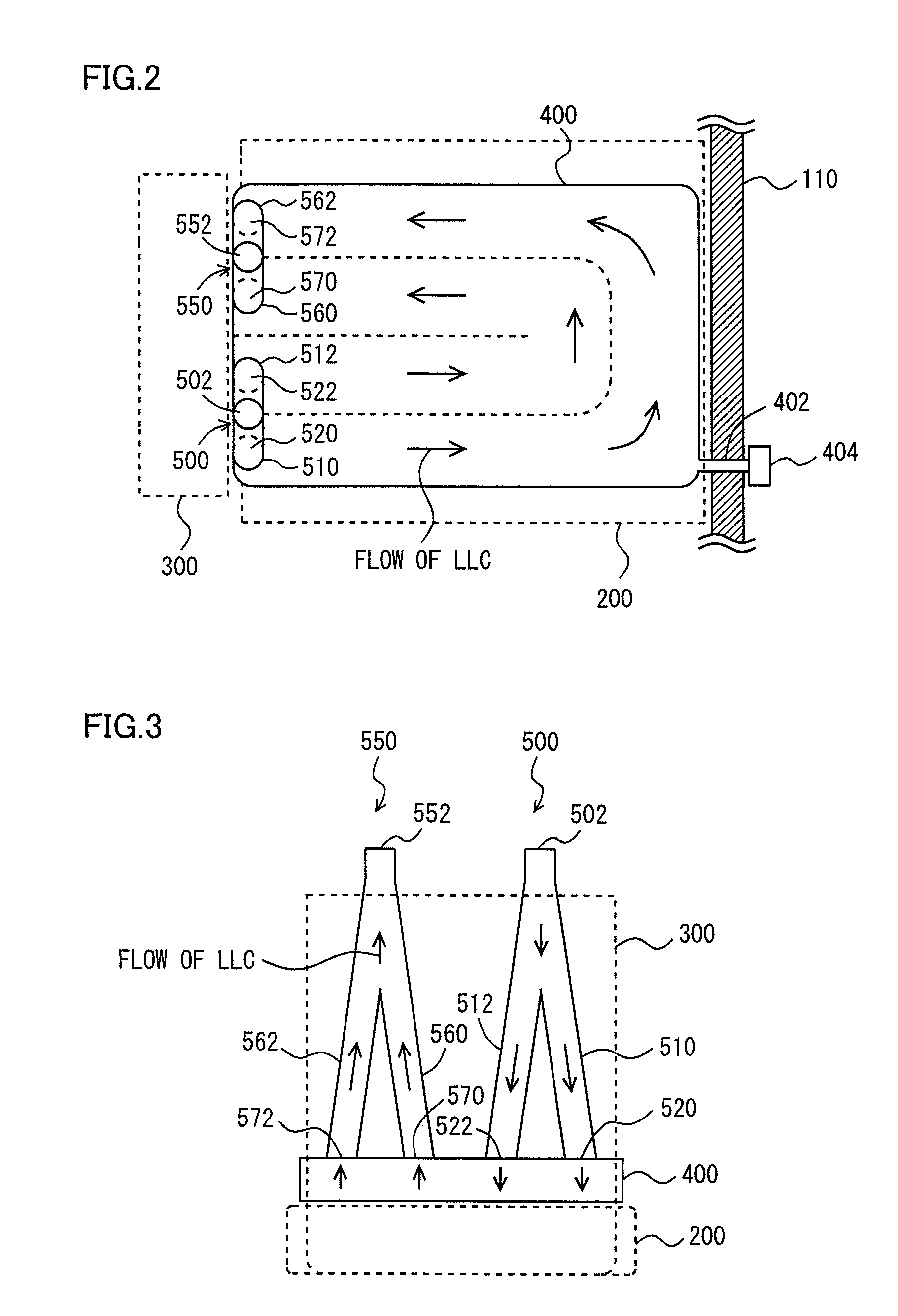
Inside a housing, there are provided a motor generator (MG), an IPM, and a smoothing capacitor. Between the MG and the IPM, there is provided a cooler through which a coolant liquid flows, provided in an inclined manner to form contact with the top face of the IPM. Between the MG and the smoothing capacitor, there are provided a first communication channel through which an LLC flows from a region outside the housing into the cooler, brought into contact with a lateral face of the smoothing capacitor, and a second communication channel through which the LLC flows from the interior of the cooler to the region outside the housing.

Description

TECHNICAL FIELD[0001]The present invention relates to the cooling technique for an inverter and capacitor accommodated integrally in a housing of a motor, particularly to the technique of suppressing heat transfer from the motor to the inverter and capacitor.BACKGROUND ART[0002]There is conventionally known an inverter-integrated motor allowing simplification and downsizing of the structure by providing an inverter and motor integrally. In recent years, there is a demand for reducing the size of the inverter-integrated motor since such inverter-integrated motors are now mounted on a vehicle (electric car, hybrid vehicle, or the like) that runs with the motor driven by an alternating current converted by the inverter. Accordingly, there is also the demand for reducing the size of the cooling structure for the motor and inverter. Japanese Patent Laying-Open No. 2003-324903, for example, discloses the approach to reduce the size of a cooling structure for an inverter-integrated motor.[...

Claims


Application Information

Patent Timeline
Patent Type & Authority Patents(United States)
IPC IPC(8): H02K9/19
CPCH02K5/20H02K9/19H02K11/048H02K11/0094H02K5/203H02K11/05
Inventor YOSHIDA, TADAFUMIYOSHINO, MASAKIHOTTA, YUTAKA
Owner TOYOTA JIDOSHA KK
Learn More