
Multiple-antenna space multiplexing system using enhancement signal detection

a multi-antenna space and signal detection technology, applied in the field of multiple-antenna space multiplexing system, can solve the problems of iterative interference cancellation, poor performance, and easy realization of linear detection methods, and achieve the effect of significantly increasing complexity caused by iterative interference cancellation

Active Publication Date: 2010-04-29
SAMSUNG ELECTRONICS CO LTD +1
View PDF4 Cites 40 Cited by
  • Summary
  • Abstract
  • Description
  • Claims
  • Application Information

AI Technical Summary

Benefits of technology

[0025]This invention provides a BLAST system using enhancement signal detection. Complexity of this system is close to a BLAST system using a traditional linear detector and the performance of system according to present invention is better than the BLAST system using sequential interference cancellation nonlinear detector.
[0034]Compared with the ZF and the ZF SIC detection method, the BER performance of this system in this invention are improved significantly. Compared with the above detection methods, in this invention, this invention has more advantages in considering the system performance, improvement and realization complexity.

Problems solved by technology

The linear detection method is easy to be realized relatively, while with poor performance.
However the significantly increased complexity caused by iterative interference cancellation is the main difficulty for the nonlinear detection to be put into practice.
The BLAST linear detection method is easy to be realized relatively, while with poor performance.
However the significantly increased complexity caused by the iterative interference cancellation is the main difficulty for the nonlinear detection to be put into practice.

Method used


Image

  • Multiple-antenna space multiplexing system using enhancement signal detection
  • Multiple-antenna space multiplexing system using enhancement signal detection
  • Multiple-antenna space multiplexing system using enhancement signal detection

Examples


Embodiment Construction

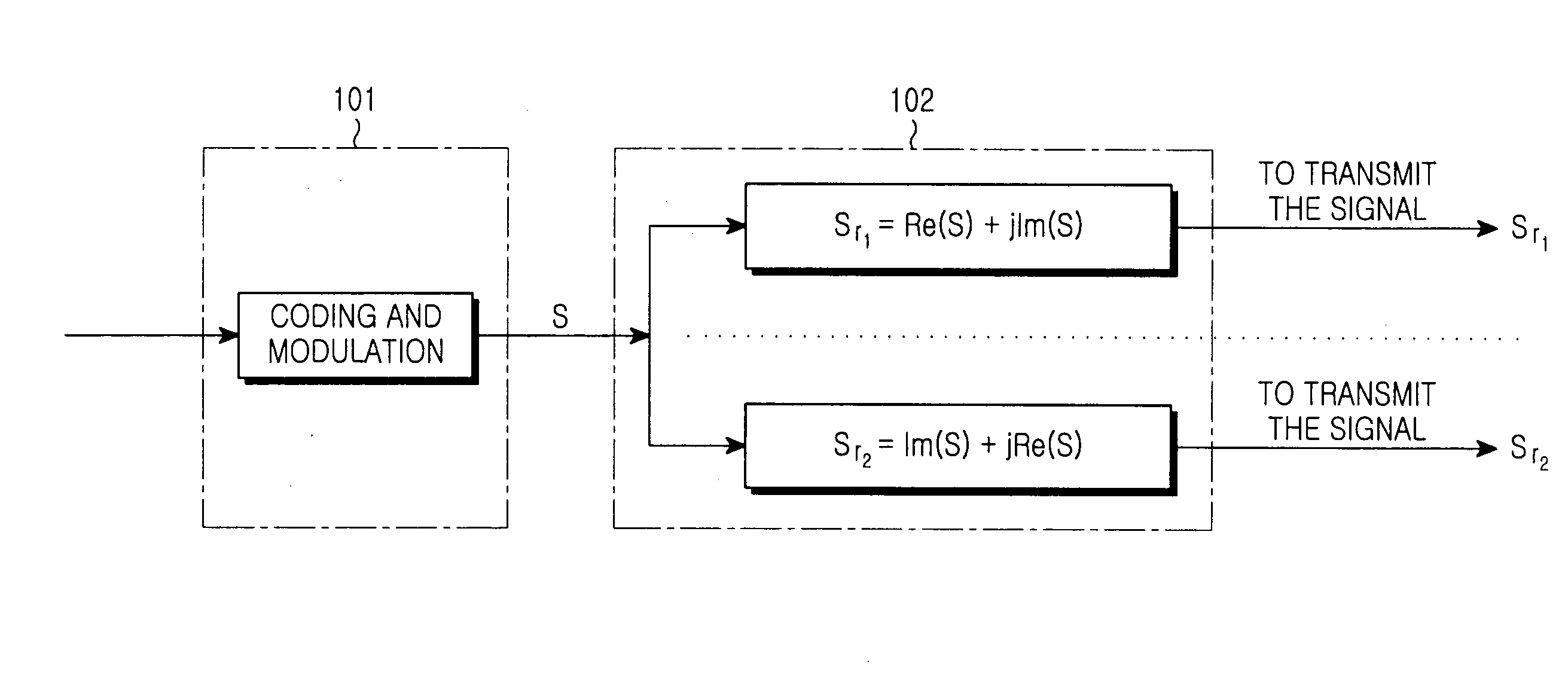
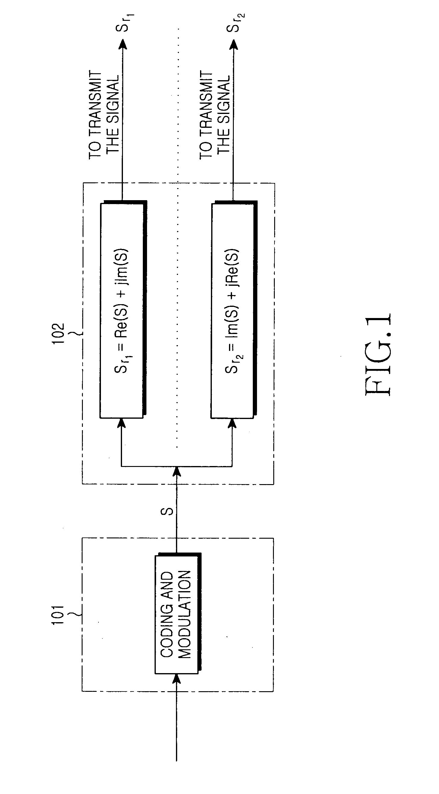
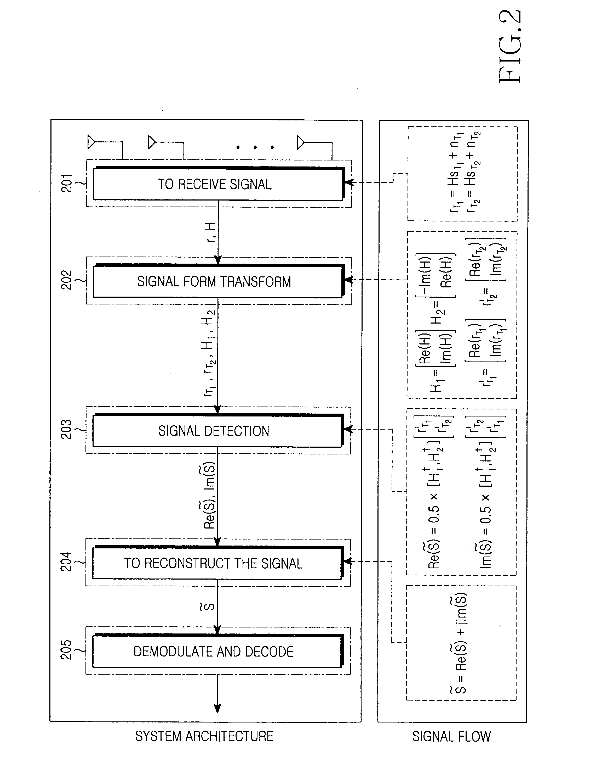
[0038]The system architecture and signaling flow according to this invention are shown in FIG. 1 and FIG. 2.

[0039]An outline of this system architecture is described in the followings:

[0040]Code modulation module for coding and modulating the bit information.

[0041]Signal transmission module for transmitting the modulated signals. The principles of this module consist in that: the signal waiting to be transmitted is s, assuming that quasi-static fading channel H remains the same between adjacent time block T1 and T2. In time block T1, the transmission signal is sT1=Re(s)+jIm(s), in time block T2, the transmission signal is sT2=Im(s)+jRe(s). Re(s) indicates a real part of the complex signal, Im(s) indicates an imaginary part of the complex signal.

[0042]Signal reception module for receiving the signals, rT1=HsT1+nT1, rT2=HsT2+nT2.

[0043]Signal form transform module for transforming the form of channel matrix H and the received signal vector r:

H1=[Re(H)Im(H)],H2=[-Im(H)Re(H)],rT1′=[Re(rT...


PUM


Abstract

The multiple-antenna space multiplexing system using enhancement signal detection comprising: a code modulation module for coding and modulating bit information; a signal transmission module for transmitting the modulated signals; a signal reception module for receiving the signals; a signal form transform module for transforming form of a channel matrix H and the received signal vector r; a signal detection module for detecting the received signals; a signal reconstruction module for reconstructing the detection results of in the signal detection module, and obtaining a detected signal; a demodulation decoding module for demodulating and decoding the output of the signal reconstruction module, and outputting bit information. Compared with the conventional detection methods, the system performance is improved in considering the realization complexity.

Description

BACKGROUND OF THE INVENTION[0001]1. Field of the Invention[0002]This invention relates to transmission of information in a multiple-antenna communication system, especially relates to a technology of transmission and detection for a multiple-antenna signal.[0003]2. Description of the Related Art[0004]With limited spectrum resources, data transmission rate can be improved effectively by using the multiple-antenna space multiplexing BLAST technology.[0005]The existing BLAST detection algorithm may be divided to linear detection (including Zero-Forcing detection (ZF), Minimum Mean Square Error Detection (MMSE) . . . ) and nonlinear detection (including Zero-Forcing and signal Interference Cancellation detection (ZF-SIC), Minimum mean Square Error and signal Interference Cancellation detection (MMSE-SIC) . . . ).[0006]The linear detection method is easy to be realized relatively, while with poor performance. Compared with the linear detection method, the nonlinear detection method may i...

Claims


Application Information

Patent Timeline
Patent Type & Authority Applications(United States)
IPC IPC(8): H04L27/06H04J99/00
CPCH04L1/0631H04L1/0656H04L25/022H04L25/0238H04L25/0242H04L25/03006H04L2025/03426H04B7/0669H04B7/0413H04B7/0697H04L5/0023H04L25/03114
Inventor CHEN, PENGKIM, YOUNG-HAK
Owner SAMSUNG ELECTRONICS CO LTD
Learn More