Vehicle travel track estimator

Active Publication Date: 2010-04-29
TOYOTA JIDOSHA KK
View PDF6 Cites 103 Cited by
  • Summary
  • Abstract
  • Description
  • Claims
  • Application Information

AI Technical Summary

Benefits of technology

[0019]As such, since the parameter indicating the sensitivity of the target vehicle to the risk is the degree of alertness of the driver of the target vehicle, it is possible to reflect the drowsiness

Problems solved by technology

However, the surrounding environment of the obstacle or the behavior of the obstacle is actually not uniform.
Therefore, the collision avoidance ap

Method used


Image

  • Vehicle travel track estimator
  • Vehicle travel track estimator
  • Vehicle travel track estimator

Examples


first embodiment

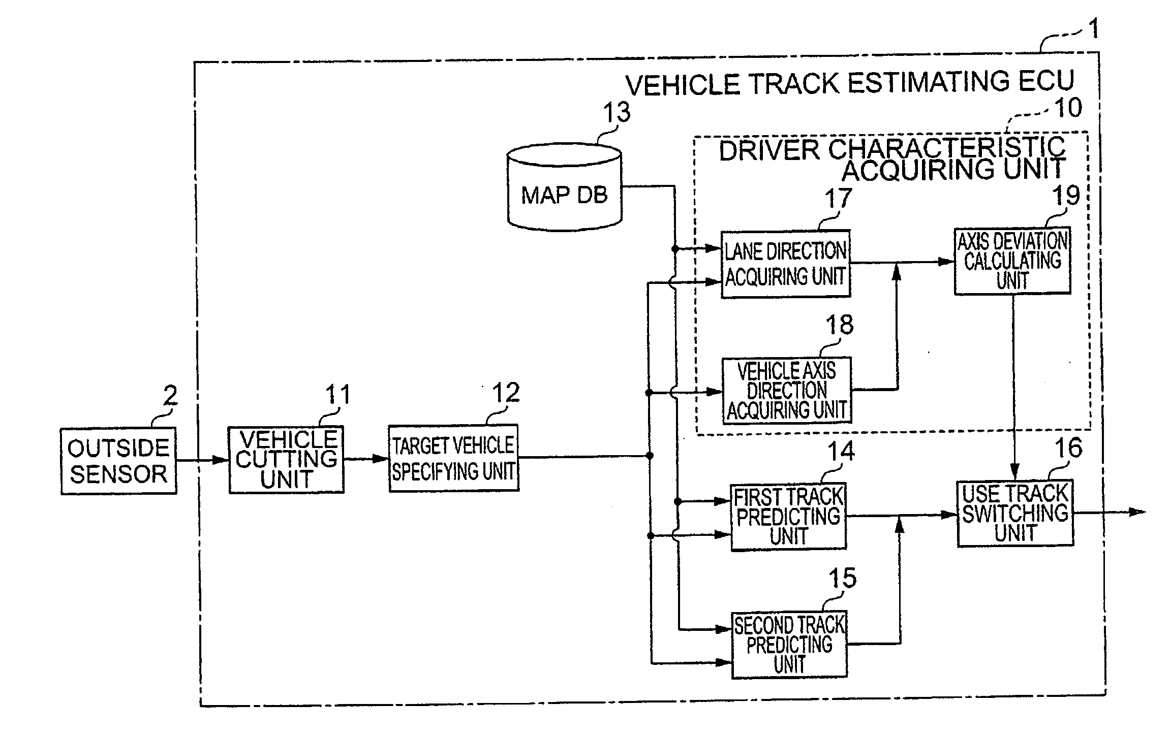
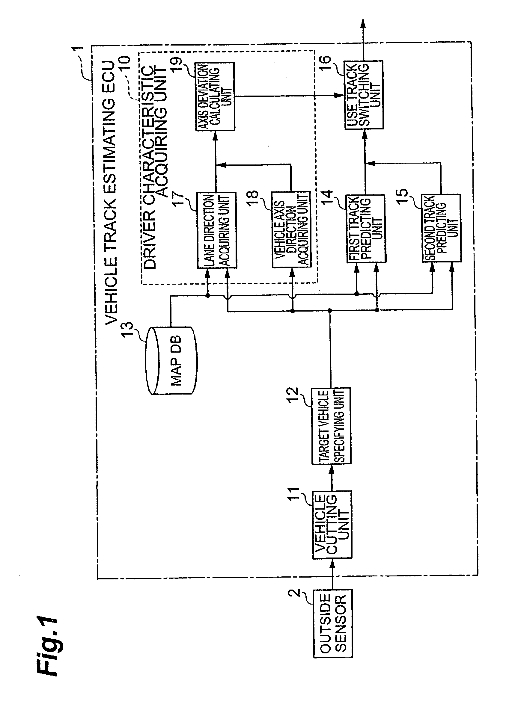
[0035]FIG. 1 is a block diagram illustrating the structure of a vehicle travel track estimator according to the invention. As shown in FIG. 1, the vehicle travel track estimator includes a vehicle track estimating ECU 1 and an outside sensor 2. The vehicle track estimating ECU 1 is a vehicle device computer for electronic control, and includes, for example, a CPU (central processing unit), a ROM (read only memory), a RAM (random access memory), and an input / output interface. In addition, the vehicle track estimating ECU 1 includes a driver characteristic acquiring unit 10, a vehicle cutting unit 11, a target vehicle specifying unit 12, a map database 13, a first track predicting unit 14, a second track predicting unit 15, and a use track switching unit 16. The driver characteristic acquiring unit 10 includes a lane direction acquiring unit 17, a vehicle axis direction acquiring unit 18, and an axis deviation calculating unit 19.

[0036]The outside sensor 2 includes, for example, a mil...

second embodiment

[0083]The cut vehicle storage unit 31 and the vehicle reading unit 32 have the same structure as the cut vehicle storage unit 21 and the vehicle reading unit 22 in the The vehicle behavior storage unit 33 of the driver characteristic acquiring unit 30 shown in FIG. 9 stores target vehicle storage information related to the speed of a target vehicle based on target vehicle information output from the target vehicle specifying unit 12 and the position of the target vehicle obtained with reference to map information read from the map database 13.

[0084]The third track predicting unit 34 stores the first prediction model read from the vehicle reading unit 32, and predicts the travel track of each of other vehicles as a third track on the basis of the speeds and positions of other vehicles based on other vehicle information read from the vehicle reading unit 22. The third track predicting unit 34 outputs the predicted travel tracks of other vehicles to the traffic predicting unit 36. The...

fourth embodiment

[0106]In addition, current state tendency may be used as the driver characteristics. The current state may include, for example, an absolute position, a relative position with respect to the road, a speed, a direction, and a tire angle. When the current state tendency is used, a predetermined threshold value may be set to the frequency of a specific current state of the target vehicle. When the frequency of the current state is more than the predetermined threshold value, a switching signal may be output. In the fourth embodiment, the type of target vehicle is identified as the vehicle characteristics. However, for example, vehicles may be classified into ‘large vehicles’ and ‘small vehicles’ without identifying the type of vehicle.

[0107]In each of the above-described embodiments, the first track predicting unit 14 and the second track predicting unit 15 calculate two travel tracks, and perform switching between the two travel tracks. However, three or more travel tracks may be calc...


PUM


Abstract

A vehicle risk level acquiring ECU calculates and acquires a plurality of courses of other vehicles around a driver's own vehicle, and acquires the predicted course of the driver's own vehicle. The vehicle risk level acquiring ECU calculates the collision probability of the driver's own vehicle as collision possibility on the basis of the predicted course of the driver's own vehicle and the plurality of courses of other vehicles.

Description

TECHNICAL FIELD[0001]The present invention relates to a vehicle travel track estimator that estimates the travel track of a target vehicle.BACKGROUND ART[0002]In recent years, a collision avoidance apparatus has been proposed which detects obstacles around a driver's own vehicle, determines the possibility that the driver's own vehicle will collide with the obstacles, and performs collision avoidance when the collision possibility is high (for example, see JP-A-7-104062). The collision avoidance apparatus predicts the track of the obstacle around the driver's own vehicle, and notifies the driver of a collision risk or automatically decelerates the driver's own vehicle when the driver's own vehicle is likely to collide with the obstacle, thereby avoiding collision.DISCLOSURE OF THE INVENTION[0003]However, the collision avoidance apparatus disclosed in JP-A-7-104062 uniformly predicts the travel track of an obstacle that is positioned around the driver's own vehicle and is likely to c...

Claims


Application Information

Patent Timeline
IPC IPC(8): G08G1/16
CPCB60W30/09B60W30/12B60W30/16B60W30/18172B60W40/072B60W40/076G05D1/027B60W2050/143B60W2550/20B60W2550/306B60W2550/402G08G1/16B60W40/09G08G1/166G08G1/167B60W2554/4041B60W2554/00B60W2556/50
Inventor KINDO, TOSHIKIASO, KAZUAKIHARADA, MASAHIRO
Owner TOYOTA JIDOSHA KK
Why Eureka
Try Eureka