Custom equations for the unfolding of sheet metal

a technology of unfolding equations and sheet metal, applied in the field of solid modeling software applications, can solve the problems of not being able to customize and/or refine the results of unfolding process, not being able to appeal to the entire user base of 3d solid modeling applications, and not being able to obtain the k factor to begin with, so as to refine the user's control over unfolding results

Active Publication Date: 2010-04-29
AUTODESK INC
View PDF5 Cites 33 Cited by
  • Summary
  • Abstract
  • Description
  • Claims
  • Application Information

AI Technical Summary

Benefits of technology

[0060]To overcome the problems of the prior art, one or more embodiments of the invention provide the ability to for a user to define a custom equation for the unfolding of a sheet metal object and link the results of the equation to the actual topology of their design (i.e., of a sheet metal object). Further, bounding conditions can be custom defined and provide the ability to refine the user's control over unfolding results on a completely extensible unfolding platform. Users can therefore build algebraic equations that contain references to topologically evaluated design measurements used to perform an unfolding analysis and calculate a developed length for a bend in the sheet metal object. With such capabilities, users no longer need to manually create large tables on a per-machine, per-material, and per-bend basis. Further, users are provided with the ability to visually interpret equations that the user has custom defined and view the results of such equations (and changes to such equations) dynamically in real time in a solid modeling application.

Problems solved by technology

However, the prior art methods for unfolding sheet metal do not provide the user with the ability to customize and / or refine the results of the unfolding process.
These requests can be very niche or industry specific and do not globally or generically appeal to the entire 3D solid modeling application user base.
Getting the K factor to begin with is another problem.
This is not easy since the exact location of the bend line is really not known.
In this regard, measuring the flange lengths up to a bend is not practical in practice.
This can lead to a lot of confusion and errors when designing and calculating flat patterns.
Further, tables can be extremely large.
In view of the above, it can be seen that the prior art fails to provide an easy mechanism to define and utilize K-factors and other bend calculations.
Thus, such manual calculations are burdensome and unmanageable for a large number of bends and cannot be interchanged from metal shop to metal shop due to the use of different machines.
Additional custom methods are not available nor are bounding conditions possible outside the inherent axes of the bend table definition (angle X bend radius).
Further, there is no capability to create and use non-linear equations to control a bend calculation.
With regard to bend tables, the prior art can only discretely approximate equations and require large, granular sets of data to obtain an adequate resolution of approximation.
Such large bend tables are inherently error prone to create and / or edit.
Further, the prior art fails to support algebraic user defined unfolding equations and bounding conditions.

Method used


Image

  • Custom equations for the unfolding of sheet metal
  • Custom equations for the unfolding of sheet metal
  • Custom equations for the unfolding of sheet metal

Examples


Embodiment Construction

[0076]In the following description, reference is made to the accompanying drawings which form a part hereof, and which is shown, by way of illustration, several embodiments of the present invention. It is understood that other embodiments may be utilized and structural changes may be made without departing from the scope of the present invention.

Overview

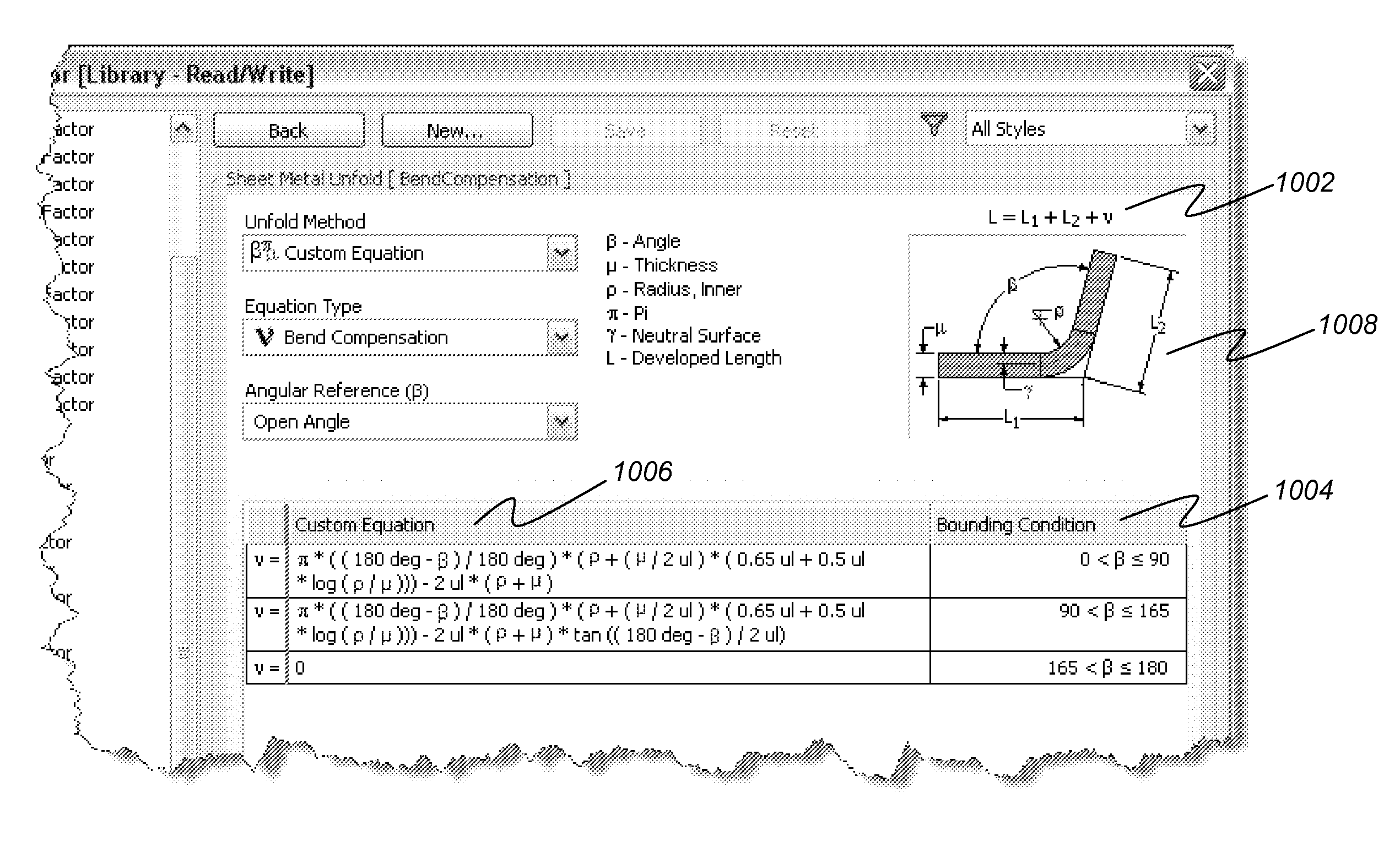
[0077]Rather than incorporating a select set of typical unfolding methods, one or more embodiments of the invention allows users to define a custom equation (non-linear or otherwise) and link the result to the actual topology of 3D design. Embodiments further allow users to apply bounding conditions to refine control over unfolding results on a completely extensible unfolding platform.

Hardware Environment

[0078]FIG. 8 is an exemplary hardware and software environment used to implement one or more embodiments of the invention. Embodiments of the invention are typically implemented using a computer 800, which generally includes, inter a...


PUM


Abstract

A computer implemented method, apparatus, and article of manufacture provide the ability to utilize custom equations for the unfolding of sheet metal in a solid modeling application. A drawing model is obtained and defines a sheet metal object in the solid modeling application. User input is accepted that defines a custom equation for a first variable that is directly used to calculate a developed length for a bend in the sheet metal object. The custom equation is converted into a standard equation that produces the developed length and is accepted by a modeling kernel of the solid modeling application. The modeling kernel dynamically displays an unfolded version of the sheet metal object based on the standard equation and the calculated developed length without exposing the standard equation to the user.

Description

BACKGROUND OF THE INVENTION[0001]1. Field of the Invention[0002]The present invention relates generally to solid modeling software applications, and in particular, to a method, apparatus, and article of manufacture for utilizing custom user-defined equations to calculate a developed length for a bend in the unfolding of sheet metal in a solid modeling application.[0003]2. Description of the Related Art[0004]Many objects and projects are built using sheet metal that is bent by a commercial shop (or other entity) based on customer specifications. However, the customer specifications must be provided to the commercial shop in an understandable manner. Many customers create their objects and designs in a three-dimensional (3D) solid modeling application. The 3D solid modeling application may be used to unfold the object to provide an illustration and details regarding how to bend a sheet metal into the object. However, the prior art methods for unfolding sheet metal do not provide the u...

Claims


Application Information

Patent Timeline
Patent Type & Authority Applications(United States)
IPC IPC(8): G06F17/50G06F17/10
CPCG06F2217/42G06F17/50G06F2113/24G06F30/00
Inventor HINDMAN, SETH A.BUSSEY, MATTHEW J.
Owner AUTODESK INC
Why Eureka
Try Eureka