
RMS Metering Devices and Methods

Active Publication Date: 2010-04-29
SILERGY SEMICON HONG KONG LTD
View PDF5 Cites 2 Cited by
  • Summary
  • Abstract
  • Description
  • Claims
  • Application Information

AI Technical Summary

Benefits of technology

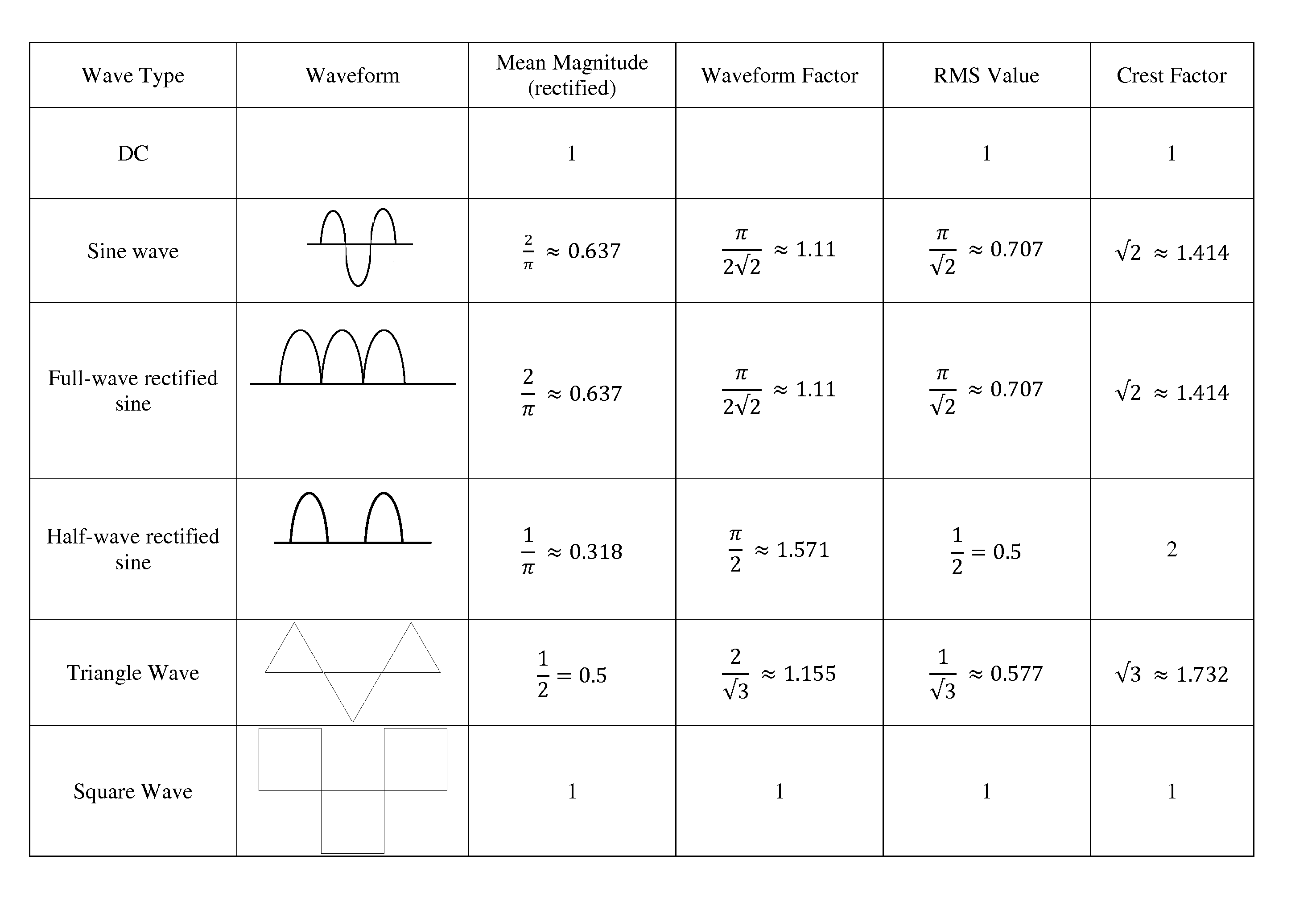
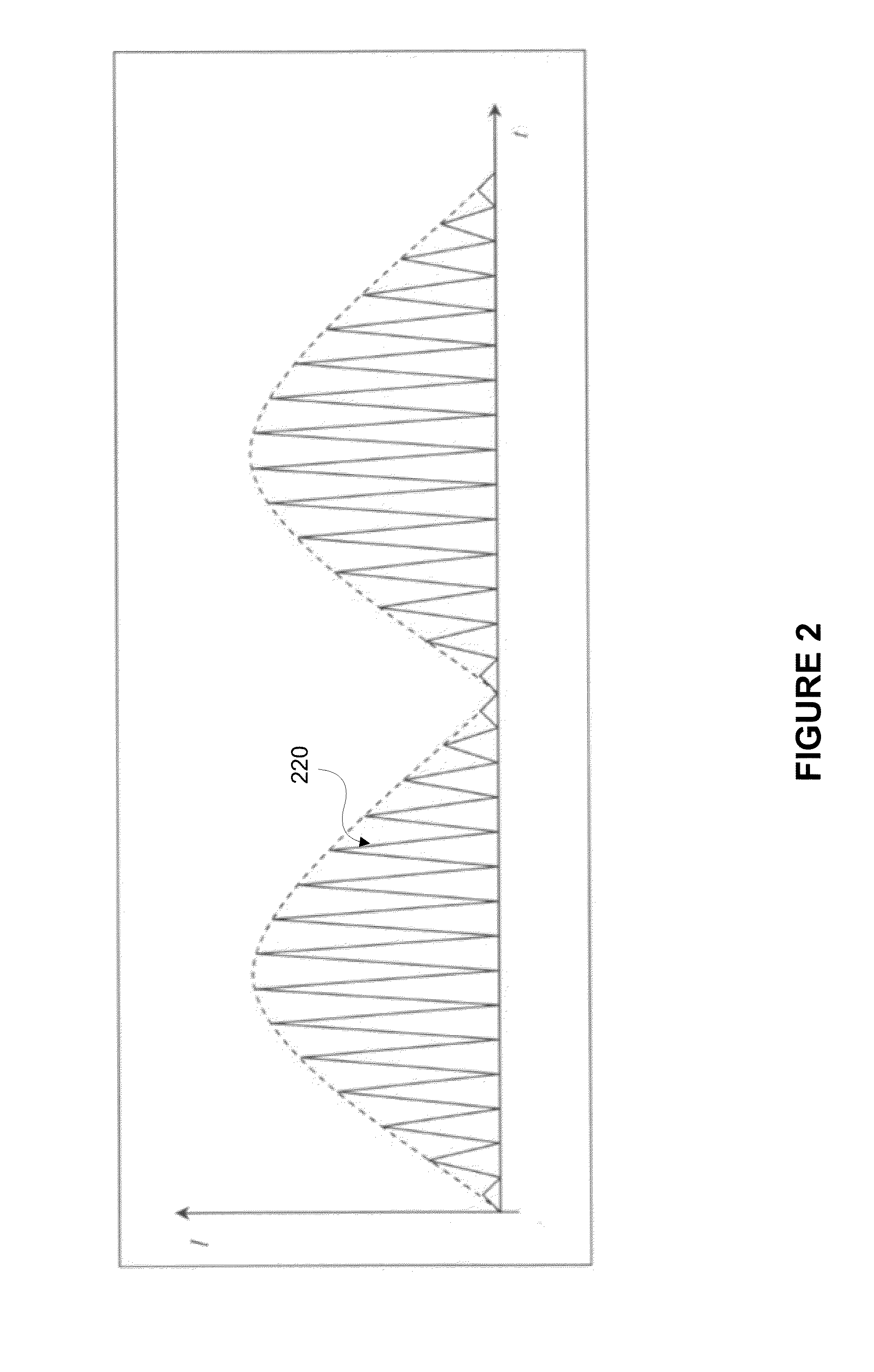
[0014]Embodiments of the present invention provide systems, devices and methods for efficiently calculating a true RMS values (either voltage or current) of an AC signal. The RMS value is generated from both high and low frequency components of the AC signal without a high speed ADC being integrated within the system. The high frequency component is processed by calculating an average current waveform of the high frequency component and approximating a corresponding RMS value using a waveform factor. The waveform factor is effectively a scalar that relates the average current waveform of the high frequency component to an appropriate RMS value. This waveform factor varies depending on the shape of the high frequency component and may be determined using various methods described herein. As a result, an accurate RMS value is identified using relatively small and cost efficient circuit architectures.

Problems solved by technology

The inclusion of such a high speed ADC within a metering system can significantly increase the die size of the system, the power consumption as well as its overall cost.
As a result, traditional metering systems usually ignore high frequency components of the AC signal when identifying certain signal characteristics such as root-mean-square (hereinafter, “RMS”) voltage and current levels and, in so doing, sacrifice a level of accuracy in these calculated levels.
Other high frequency components may also be present on the AC signal, all of which complicate an accurate determination of RMS voltage and current levels of the signal.
The cost of this high speed ADC is usually too high for a commercially feasible metering device so higher frequency components were ignored and certain RMS calculations contained a corresponding error.
As previously discussed, the failure to include high frequency components within these operations results in error within one or more of these readings.
For example, in certain instances the RMS current reading may be inaccurate by as much as twenty percent from the true RMS current of the AC signal because the high frequency current component is disregarded.
Failure to properly measure or calculate power, RMS voltage and RMS current levels may lead to mismanagement of the devices and possible damage.

Method used


Image

  • RMS Metering Devices and Methods
  • RMS Metering Devices and Methods
  • RMS Metering Devices and Methods

Examples


Embodiment Construction

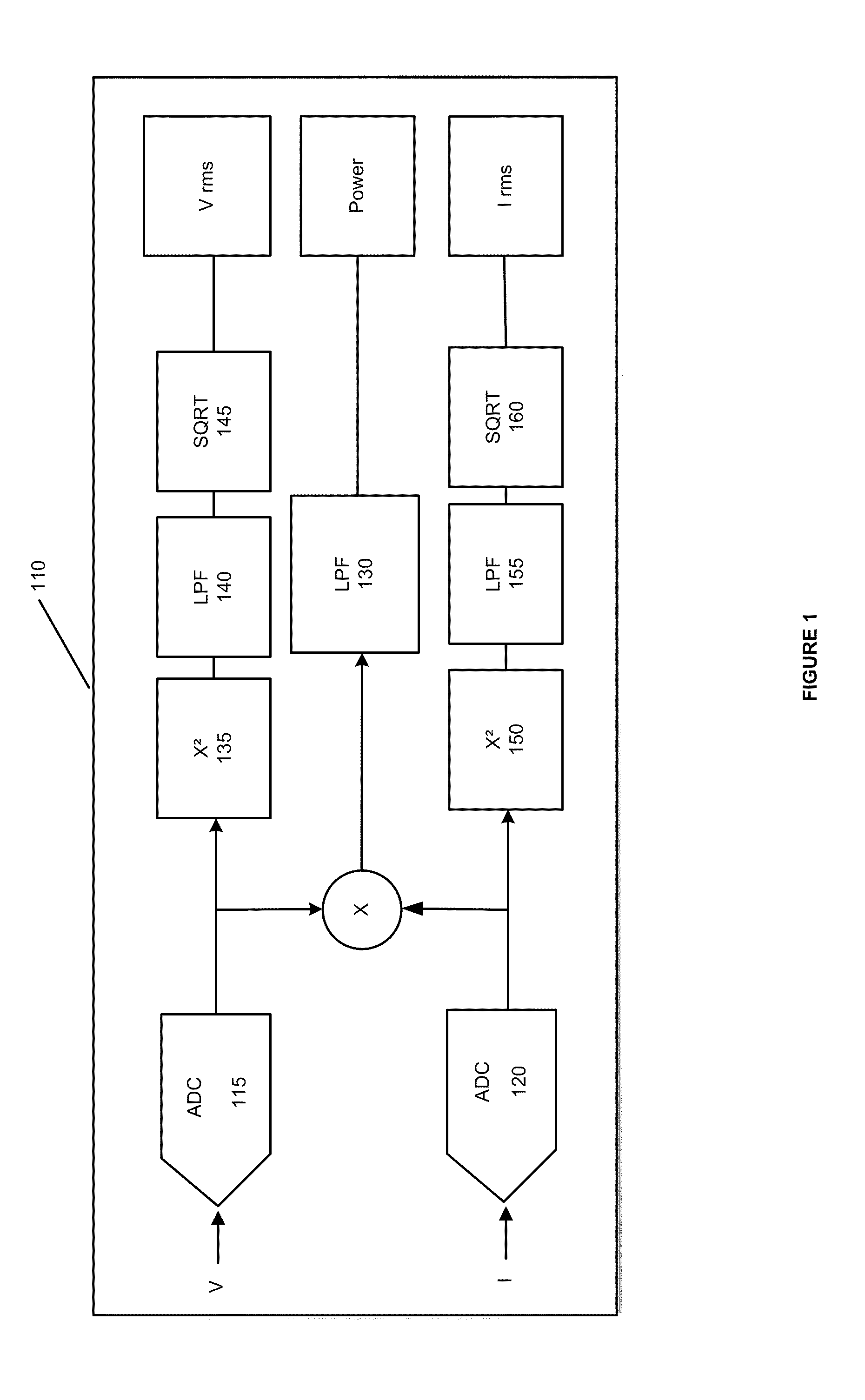
[0023]In the following description, for purpose of explanation, specific details are set forth in order to provide an understanding of the invention. It will be apparent, however, to one skilled in the art that the invention may be practiced without these details. One skilled in the art will recognize that embodiments of the present invention, some of which are described below, may be incorporated into a number of different electrical components, circuits, devices and systems. The embodiments of the present invention may function in various different types of environments wherein impedance matching is relevant including high frequency RF applications. Structures and devices shown below in block diagram are illustrative of exemplary embodiments of the invention and are meant to avoid obscuring the invention. Furthermore, connections between components within the figures are not intended to be limited to direct connections. Rather, connections between these components may be modified,...


PUM


Abstract

Embodiments of the present invention provide systems, devices and methods for efficiently calculating a true RMS values (either voltage or current) of an AC signal. The RMS value is generated from both high and low frequency components of the AC signal without a high speed ADC being integrated within the system. The high frequency component is processed by calculating an average current waveform of the high frequency component and approximating a corresponding RMS value using a waveform factor. The waveform factor is effectively a scalar that relates the average current waveform of the high frequency component to an appropriate RMS value.

Description

CROSS REFERENCE TO RELATED PATENT APPLICATIONS[0001]This application claims priority to U.S. Provisional Application Ser. No. 61 / 109,424, entitled “RMS Metering Devices and Methods,” filed Oct. 29, 2008, which application is incorporated herein by reference in its entirety.BACKGROUND[0002]A. Technical Field[0003]The present invention relates generally to metering technologies, and more particularly, to efficient and accurate methods of calculating root-mean-square values of an alternating current within a metering device.[0004]B. Background of the Invention[0005]The importance of efficiently and accurately measuring current, voltage and power levels of an alternating current (hereinafter, “AC”) signal is well understood by one of skill in the art. Oftentimes, an accurate measurement of certain types of current and voltage levels requires that both low frequency and high frequency components of the AC signal are addressed in measurement or calculation processes. The measurement of hi...

Claims


Application Information

Patent Timeline
IPC IPC(8): G06F7/38G01R19/00
CPCG01R19/0007G01R29/04G01R21/133G01R19/02
Inventor KWAK, SUNG UNGVICTOR, LEVITANG, KENNETH
Owner SILERGY SEMICON HONG KONG LTD
Learn More