Spacer profile for a spacer frame for an insulating window unit and insulating window unit

a technology of spacer profiles and insulating windows, which is applied in the direction of doors/windows, building components, construction, etc., can solve the problems of reducing the chamber volume of desiccating material, reducing the effect of wrinkle formation, and reducing the problem of wrinkle formation

Active Publication Date: 2010-05-06
TECHNOFORM GLASS INSULATION HLDG
View PDF25 Cites 10 Cited by
  • Summary
  • Abstract
  • Description
  • Claims
  • Application Information

AI Technical Summary

Benefits of technology

[0015]It is an object of the invention to provide improved spacer profiles, which preferably fulfill the “warm edge” conditions and reduce the problem of wrinkle formation while maximizing the chamber volume for the desiccating material. Improved methods for manufacturing such spacer profiles and improved insulating window unit with such spacer profiles are alternate objects of the invention.
[0023]If the profile or elongation portion has a bent, angled and / or folded configuration, the length (in the cross-section perpendicular to the longitudinal direction) of the profile or elongation portion, and thus the mass of the diffusion barrier film additionally introduced in this region or area of the spacer profile, can be significantly increased. A displacement of the bend line results therefrom, which further results in a reduction of wrinkle formation. Furthermore, the sag is substantially reduced, because the bent, angled and / or folded profile / elongation portion adds significant strength to the structural integrity of the bent spacer frame.

Problems solved by technology

Such metal spacer profiles can not, however, fulfill “warm edge” conditions.
Although a spacer, which exclusively consists of a synthetic material having a low heat conduction value, could be expected to fulfill the “warm edge” conditions, the requirements of diffusion impermeability and strength would be very difficult to satisfy.
When the spacer profile is bent, in particular when cold bending techniques are used, there is a problem of wrinkle formation at the bends (see FIG. 3c).
According to the solution known from EP 1 017 923 A1, the problem of wrinkle formation has been well solved, but the space available in the chamber for the desiccating material is not satisfactory, in particular for small distances between panes, i.e. separation distances less than 12 mm, and more particularly for separation distances of 6, 8 or 10 mm.
Moreover, according to both solutions, when the spacer profile is intended to be utilized in a large frame, the problem of considerable sag along unsupported, lengthy portions of the spacer profile exists (see FIGS. 3a and 3b).

Method used


Image

  • Spacer profile for a spacer frame for an insulating window unit and insulating window unit
  • Spacer profile for a spacer frame for an insulating window unit and insulating window unit
  • Spacer profile for a spacer frame for an insulating window unit and insulating window unit

Examples


first embodiment

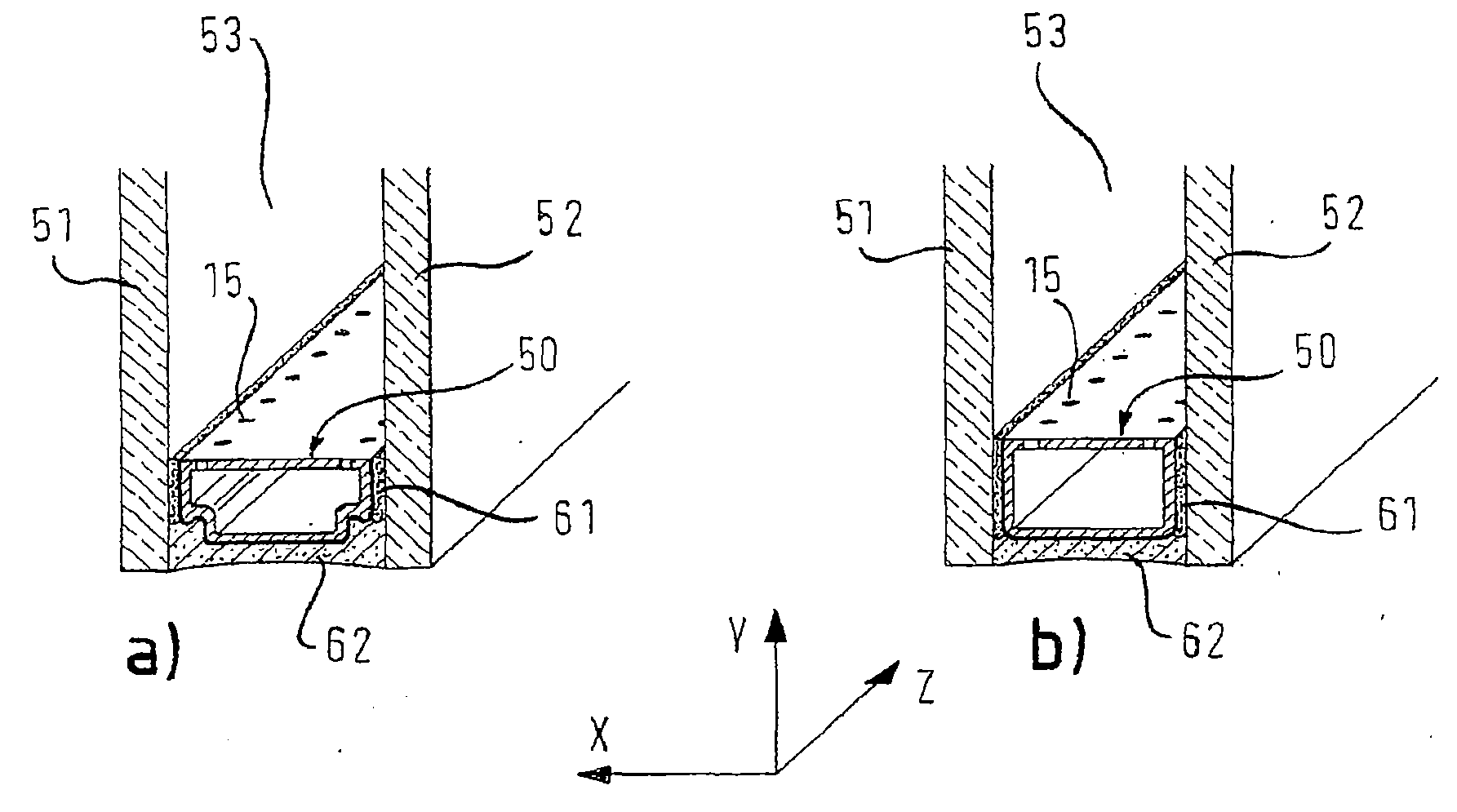
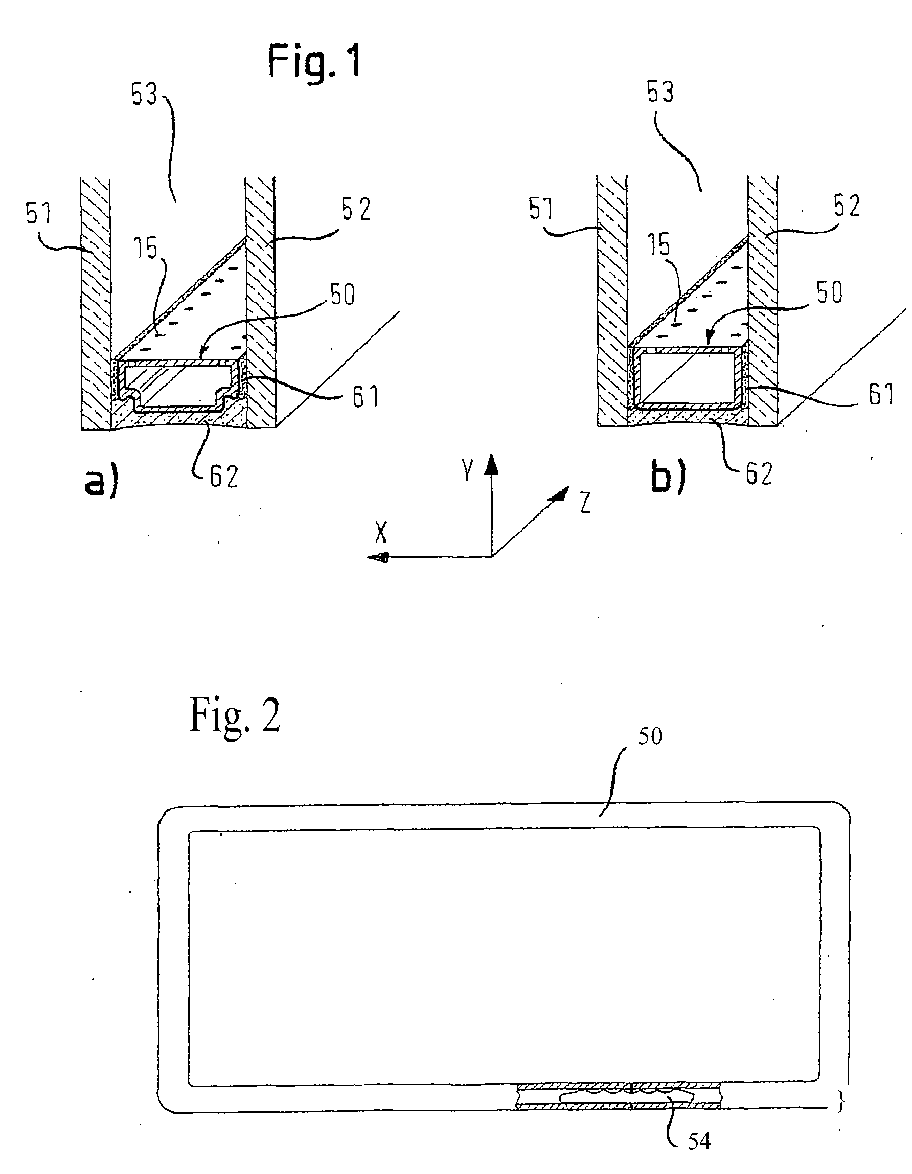
[0038]In FIGS. 1, 4-9 and 11, a so-called W-configuration of the spacer profile is shown in each a) view and a so-called U-configuration is shown in each b) view. A spacer profile will now be described with reference to FIGS. 4a) and 4b).

[0039]In FIGS. 4a) and 4b), the spacer profile is shown in cross-section perpendicular to a longitudinal direction, i.e. along a slice in the X-Y plane, and extends with this constant cross-section in the longitudinal direction. The spacer profile comprises a height h1 in the height direction Y and is comprised of a profile body 10, which is formed from a first material. The first material is preferably an elastic-plastic deformable, poor heat conducting (insulating) material.

[0040]Herein, the term “elastic-plastic deformable” preferably means that elastic restoring forces are active in the material after a bending process, as is typically the case for synthetic materials for which only a part of the bending takes place with a plastic, irreversible...

second embodiment

[0059]In FIGS. 5a) and 5b), a spacer profile is shown in cross-section in the X-Y plane.

[0060]The second embodiment differs from the first embodiment in that the elongation portions 31, 32 are almost double the length of the first embodiment, whereby the elongation length 11 stays the same. This is achieved by including a second bend (180°) in the profiles 31b, 32b and by extending the portion of the elongation portion, which is continuous with the second end, likewise in the traverse direction X, but now to the outside. A substantially longer length of the elongation portion is thereby ensured, whereby the closest possible proximity to the inner side of the spacer profile is maintained.

[0061]In addition, a part of the material of the profile body is enclosed on three sides by the profiles 31b, 32b. These enclosures result in that, during a bending process that includes compression, the enclosed material acts as an essentially incompressible volume element.

third embodiment

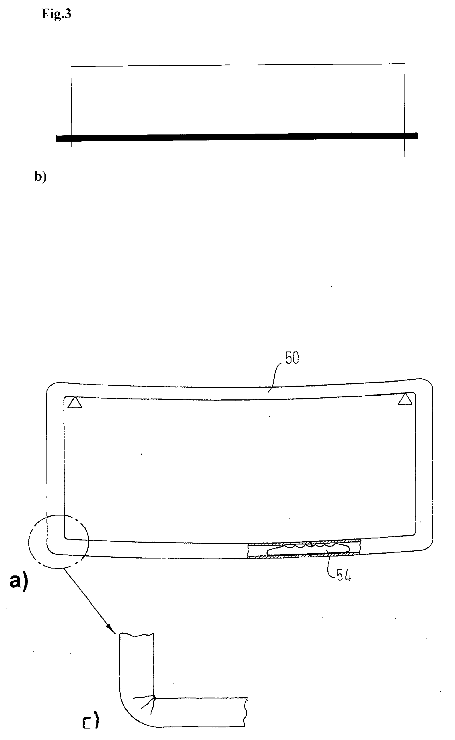
[0062]Referring to FIGS. 6a) and 6b), a spacer profile will be described, wherein the areas surrounded by a circle respectively in views a) and b) are shown enlarged in FIGS. 6c) and d). According to the embodiment shown in FIG. 6, the diffusion barrier film 30, inclusive of the elongation portions 31, 32, extends completely along the outside of the profile body 10. The elongation portions 31, 32 and their profiles 31c, 32c are thus visible on the inner side (the “outside” facing the space between the window panes) in the assembled state, because the elongation portions 31, 32 are not covered at the inner side by the material of the profile body, but rather are exposed. According to this embodiment, the elongation portion is arranged as close as possible to the inner side.

[0063]The embodiment shown in FIG. 6 could be modified so that the elongation portion 31, 32 is elongated and, similar to the embodiment shown in FIG. 5 (or also in FIGS. 7-9), extends into the interior of the acc...


PUM

PropertyMeasurementUnit
thickness d1aaaaaaaaaa
thicknessaaaaaaaaaa

Abstract

A spacer profile (50) for a spacer profile frame mountable in the edge area of an insulating window unit for forming an intervening space (53) between window panes (51, 52), has a profile body (10) made of synthetic material and comprises one or more chambers (20) for accommodating hygroscopic material. A metal film (30) encloses the profile body on three-sides such that, in the bent / assembled state of the spacer profile, the non-enclosed inner side of the profile body is directed towards the intervening space between the window panes. The not-enclosed inner side of the profile body comprises openings (15) for moisture exchange between hygroscopic material accommodated in the chamber(s) and the intervening space between the window panes. The metal film comprises a profile (31a-g, 32a-g) on each end directed towards the intervening space of the window panes. Each profile has at least one edge or bend.

Description

CROSS-REFERENCE[0001]This application is a division of U.S. patent application Ser. No. 11 / 575,020, filed on Dec. 7, 2007, which claims the benefit of priority of PCT Patent Application No. PCT / EP2005 / 009349, filed Aug. 30, 2005.TECHNICAL FIELD[0002]The present invention relates to spacer profiles and to insulating window units incorporating the present spacer profiles.DESCRIPTION OF THE BACKGROUND ART[0003]Insulating window units having at least two window panes, which are held apart from each other in the insulating window unit, are known. Insulating windows are normally formed from an inorganic or organic glass or from other materials like Plexiglas. Normally, the separation of the window panes is secured by a spacer frame (see reference number 50 in FIG. 1). The spacer frame is either assembled from several pieces using connectors or is bent from one piece (see FIG. 2), so that then the spacer frame 50 is closable by a connector 54 at only one position.[0004]Various designs have...

Claims


Application Information

Patent Timeline
Patent Type & Authority Applications(United States)
IPC IPC(8): E04C2/54E04C2/34E06B7/12
CPCE06B2003/6638E06B3/66319E06B3/66323E06B3/67304
Inventor BRUNNHOFER, ERWINSOMMER, PETRALENZ, JORG
Owner TECHNOFORM GLASS INSULATION HLDG
Why Eureka
Try Eureka