Turbine integrated bleed system and method for a gas turbine engine

a gas turbine engine and integrated bleed technology, applied in the direction of machines/engines, sustainable transportation, mechanical equipment, etc., can solve the problems of not meeting the requirements of ecs interface, limited temperature capability of structures compared to metal alloys, and throttling inefficiencies, so as to minimize throttling inefficiencies

Inactive Publication Date: 2010-05-06
GENERAL ELECTRIC CO
View PDF8 Cites 109 Cited by
  • Summary
  • Abstract
  • Description
  • Claims
  • Application Information

AI Technical Summary

Benefits of technology

[0005]These and other shortcomings of the prior art are addressed by the present invention, which provides a turbine integrated bleed system (TIBS) which is effective to extract HPC and fan bleed air from a turbine engine and provides low pressure, low temperature airflow to an aircraft environmental control system while minimizing throttling inefficiencies and the need for bleed air precooling.

Problems solved by technology

These structures have limited temperature capability compared to metal alloys.
Conventional ECS interfaces, utilizing engine bleed air and a fan air precooler, can not meet this requirement without significantly increasing the size of the precooler.
While effective to provide low-pressure, low-temperature bleed air, this requires a separate air inlet to efficiently entrain ambient air and considerable electrical power to drive the ECS compressors.
The electrical power requirements can require an undesirable increase in the size of the engine mounted generators.

Method used


Image

  • Turbine integrated bleed system and method for a gas turbine engine
  • Turbine integrated bleed system and method for a gas turbine engine
  • Turbine integrated bleed system and method for a gas turbine engine

Examples


Embodiment Construction

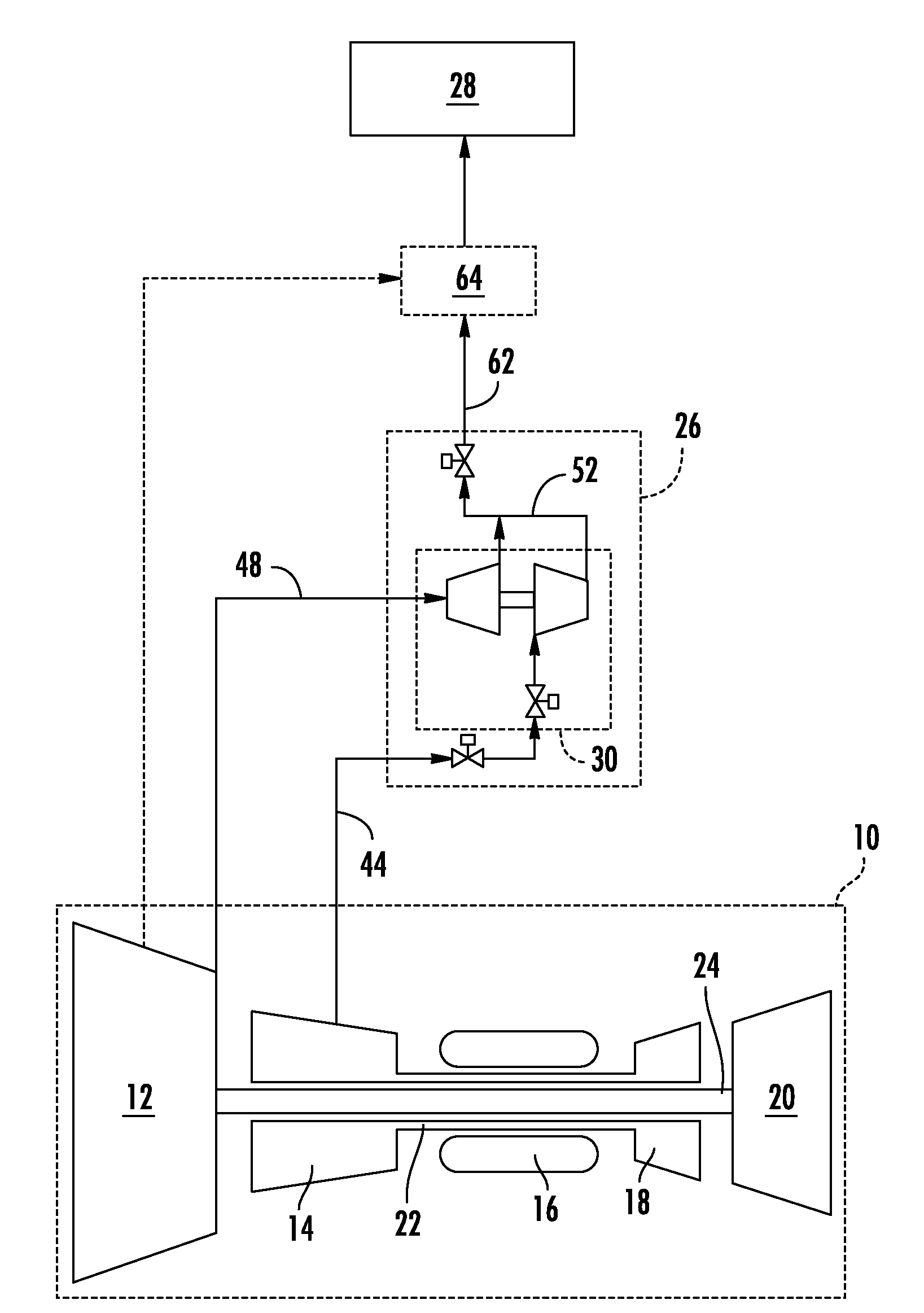
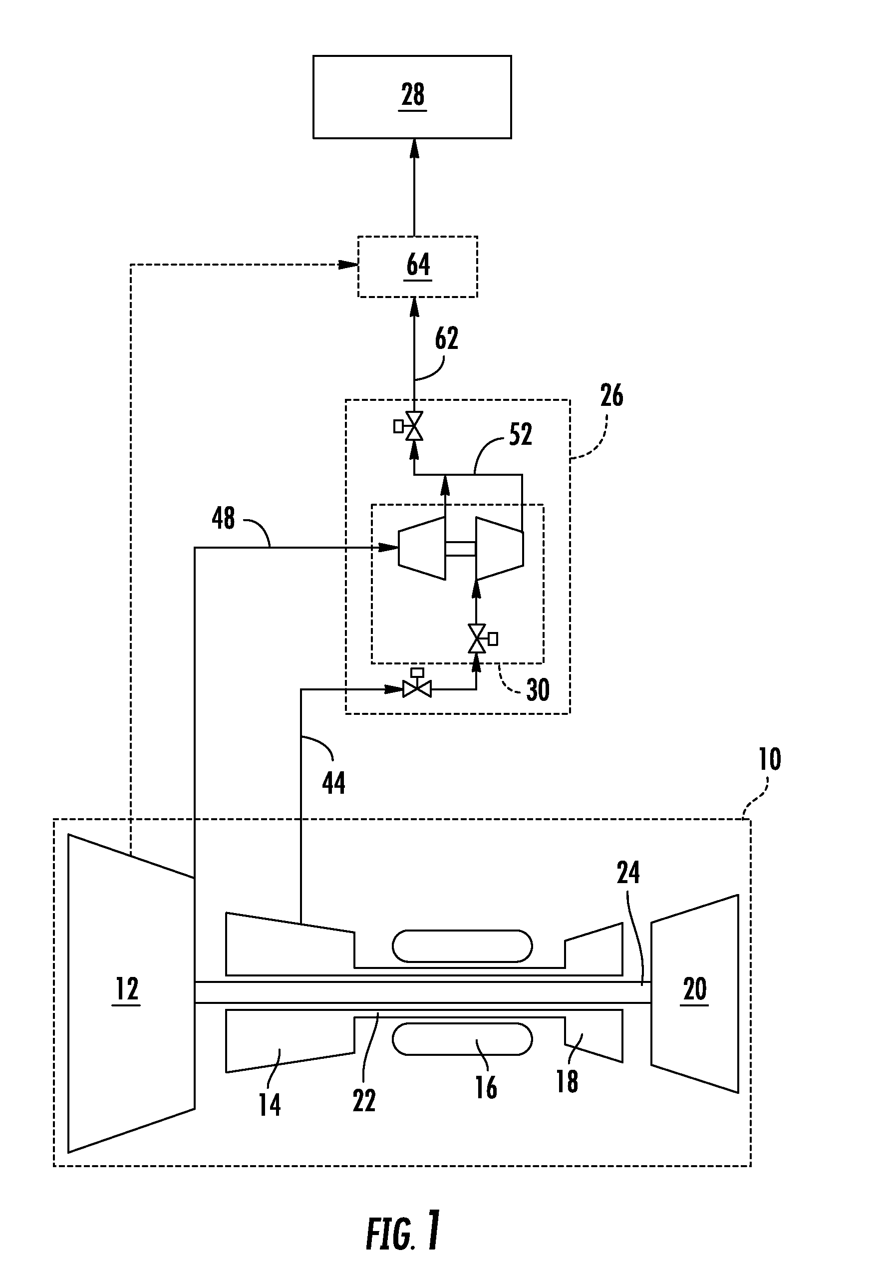
[0012]Referring to the drawings wherein identical reference numerals denote the same elements throughout the various views, FIG. 1 depicts schematically the elements of an exemplary gas turbine engine 10 having a fan 12, a high pressure compressor 14, a combustor 16, a high pressure turbine 18, and a low pressure turbine 20, all arranged in a serial, axial flow relationship. Collectively the high pressure compressor 14, the combustor 16, and the high pressure turbine 18 are referred to as a “core”. The high pressure compressor 14 provides compressed air that passes into the combustor 12 where fuel is introduced and burned, generating hot combustion gases. The hot combustion gases are discharged to the high pressure turbine 18 where they are expanded to extract energy therefrom. The high pressure turbine 18 drives the compressor 10 through an outer shaft 22. Pressurized air exiting from the high pressure turbine 18 is discharged to the low pressure turbine 20 where it is further expa...


PUM


Abstract

A bleed system for a gas turbine engine includes: (a) a bleed air turbine having a turbine inlet adapted to be coupled to a source of compressor bleed air at a first pressure; (b) a bleed air compressor mechanically coupled to the bleed air turbine, and having a compressor inlet adapted to be coupled to a source of fan discharge air at a second pressure substantially lower than the first pressure; and (c) a mixing duct coupled to a turbine exit of the bleed air turbine and to a compressor exit of the bleed air compressor.

Description

BACKGROUND OF THE INVENTION[0001]This invention relates generally to gas turbine engines and more particularly to methods and apparatus for extracting bleed air in such engines.[0002]Turbine-powered aircraft conventionally incorporate environmental control systems (ECS) which control aircraft cabin temperature by the amount and temperature of the bleed air extracted from the engine. Historically, ECS have used engine bleed air that is extracted from a high pressure compressor (HPC), throttled (pressure reduced), and cooled by a heat exchanger (“precooler”) using fan bleed air. This is possible because metal airframes are tolerant of exposure to high temperature bleed air. Bleed air is also used to provide anti-icing to the aircraft, and must be at high temperature for this purpose—typically about 204° C. (400° F.).[0003]Future aircraft will replace some or all of these metallic structures with composite materials to reduce weight and improve overall efficiency. These structures have...

Claims


Application Information

Patent Timeline
Patent Type & Authority Applications(United States)
IPC IPC(8): F02C7/047F02C6/08
CPCF02C6/08F02C9/18Y02T50/672F05D2220/327Y02T50/60
Inventor COFFINBERRY, GEORGE ALBERTLEAMY, KEVIN RICHARD
Owner GENERAL ELECTRIC CO
Why Eureka
Try Eureka