Data center cooling device and method

a cooling device and data center technology, applied in the field of cooling systems, can solve the problems of system redundancy, system incompatibility with redundancy, and inefficient fan size,

Inactive Publication Date: 2010-05-06
BELL PROD
View PDF22 Cites 74 Cited by
  • Summary
  • Abstract
  • Description
  • Claims
  • Application Information

AI Technical Summary

Problems solved by technology

These design considerations have changed considerably over time as computing systems of the type typically located within a data center consume considerable amounts of energy while generating heat necessitating CRAC systems of greater efficiency.
Small fans are employed even though smaller fans are generally more inefficient than those which are larger.
These systems do not integrate redundancy in the form of additional heat exchange area in order to make them more efficient.
It is quite apparent that previously suggested CRAC systems made no attempt to maximize operating efficiencies as most prior designs were created well before energy became as expensive as it is today and before the explosive use of Internet-based communications and information downloading created such a severe impact upon energy usage and resultant heat generation.
Since the chiller and “free cooling” cycle cannot operate simultaneously, free cooling of this type can only be used when the cooling capacity of water tower 11 is sufficient to meet the entire building load.

Method used


Image

  • Data center cooling device and method
  • Data center cooling device and method
  • Data center cooling device and method

Examples


Embodiment Construction

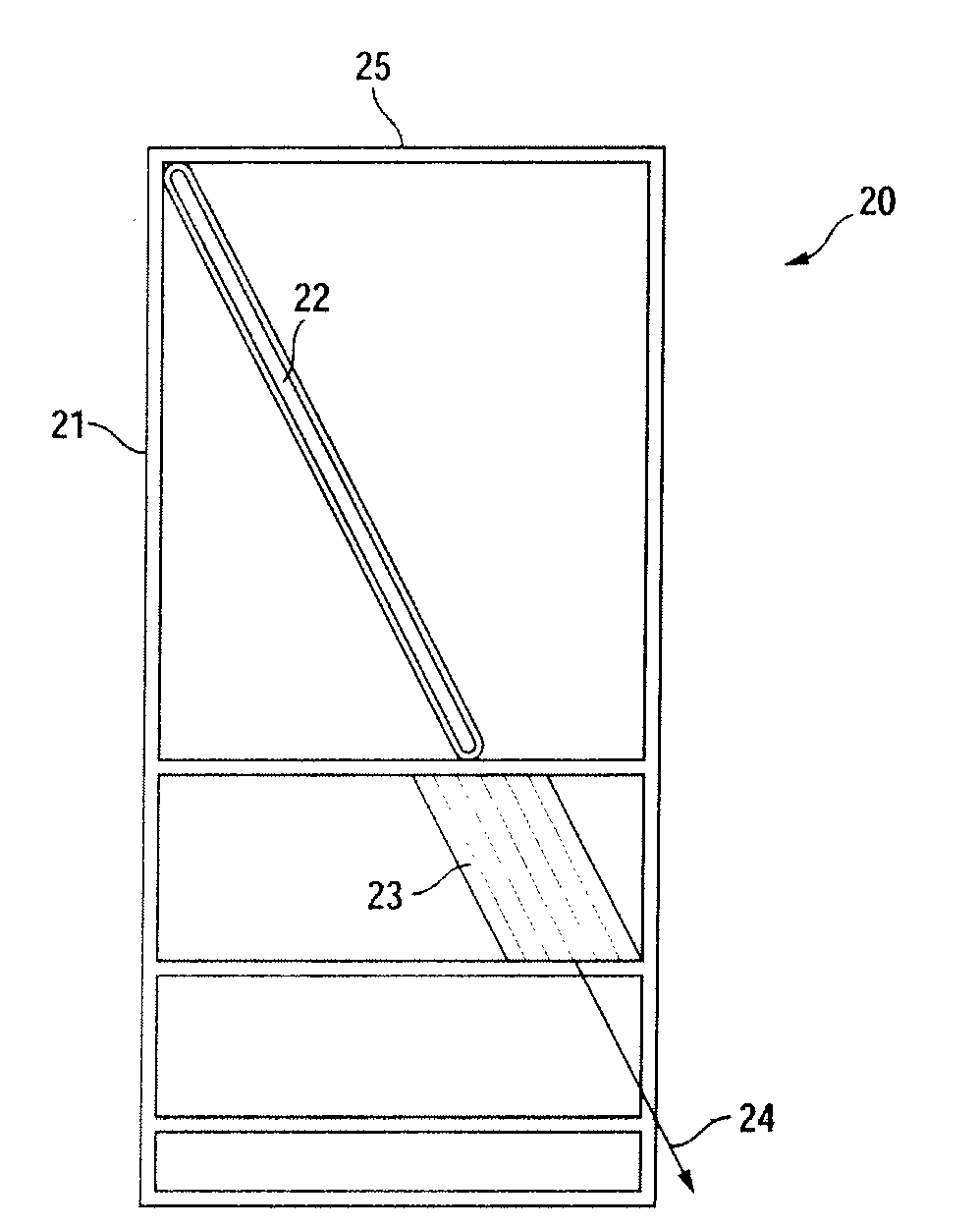
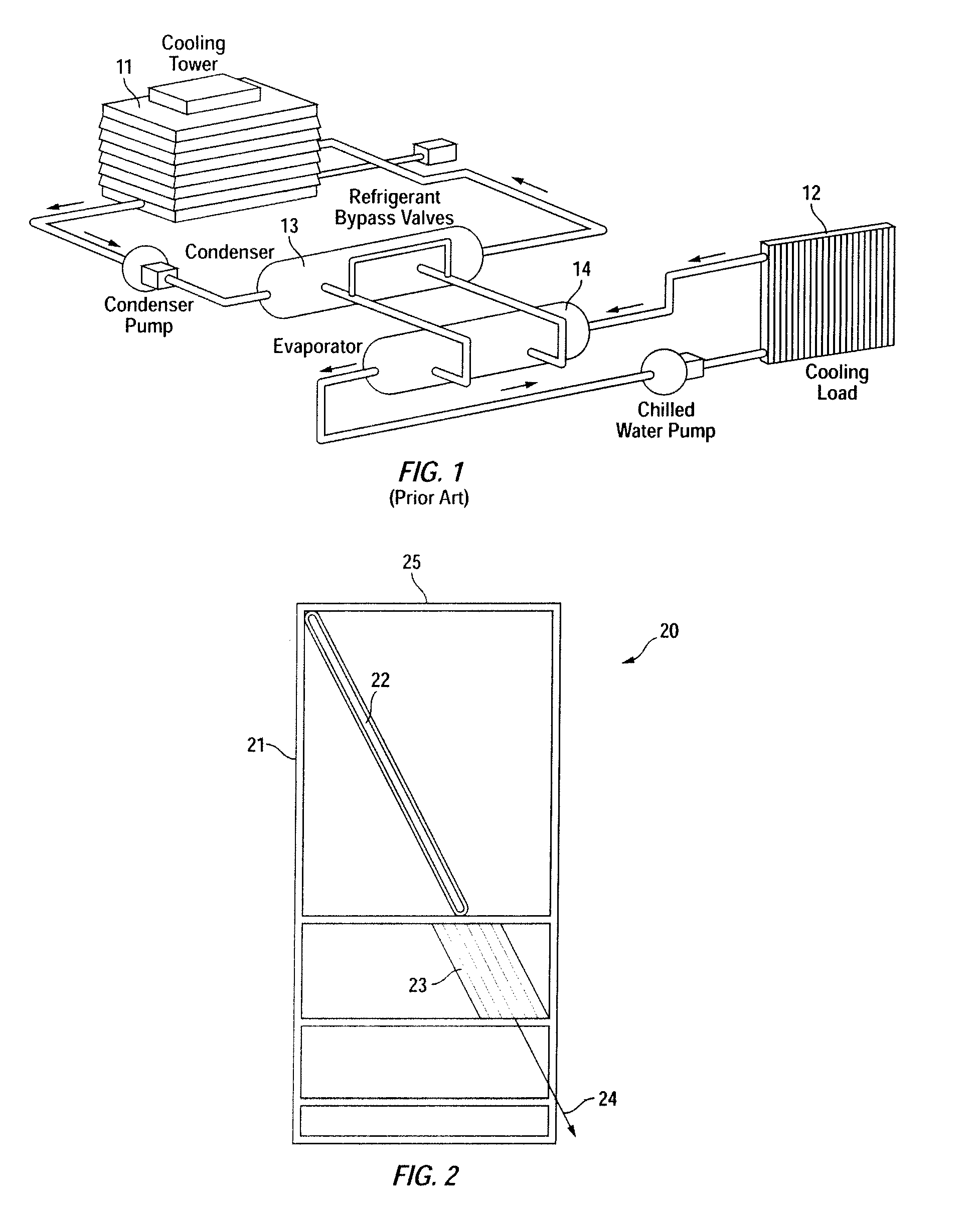
[0022]Turning first to FIG. 2, housing 20 is depicted with its side walls removed for illustrative purposes. Frame members 21 support sets of evaporator coils 22 receiving coolant from compressors and related hardware located external to the data center being cooled.

[0023]In operation, ambient air within the data center is drawn through open top 25 passed sets of evaporator coils 22 through the use of prop or axial fans 23. Ideally, multiple fans are employed sufficient to maintain a positive static pressure within a space beneath the flooring. Although not shown, cool air created by housing 20 is discharged proximate racks of circuit boards and similar solid state devices through openings strategically located proximate thereto.

[0024]A feature of the present invention is the orientation of fans 23 in directing cooled air in the direction of arrows 24. CRAC units of the prior art generally employ centrifugal fans that blow air directly at the floor. This increases the static pressur...


PUM


Abstract

A cooling system and method for cooling devices housed in a data center. A cabinet housing a set of condenser coils is located within the data center positioned on its floor and including fans for drawing air passed the condenser coils and exiting the device angularly to the floor of the data center. The present invention also contemplates the use of redundant compressors and condensers, a system that includes a secondary evaporator coil and configuration which enables the device, under certain conditions, to bypass its compressor.

Description

TECHNICAL FIELD[0001]The present invention involves a cooling system and method for its operation used for cooling devices in a data center. Data centers are rooms that contain electronic systems generally arranged on racks, the standard rack being defined by the EIA as an enclosure approximately 78″ high, 24″ wide and 40″ deep. These racks are employed to house printed circuit board-based devices which, under normal operation, can generate significant amounts of heat. For the proper operation of such devices and for maintaining them throughout their normal life cycle, proper temperature and humidity must be maintained.BACKGROUND OF THE INVENTION[0002]Historically, computer room air conditioning (CRAC) systems were manufactured by those who supplied residential and commercial air conditioning systems, generally. The design philosophy was to build such systems at the lowest possible cost, that is, the cost of manufacturing being more important than the operational cost of the system....

Claims


Application Information

Patent Timeline
Patent Type & Authority Applications(United States)
IPC IPC(8): F25D23/12F25B1/00
CPCF25B2400/0401F25B2400/06F25B2700/2106F25D16/00H05K7/20827F25B41/003
Inventor COCKRELL, RICHARD ERWIN
Owner BELL PROD
Why Eureka
Try Eureka