
Integrated bypass diode assemblies for back contact solar cells and modules

a solar cell and back contact technology, applied in the field of integrated bypass diode assemblies, can solve the problems of reducing the module performance in the system, introducing another field degradation problem, and affecting the output of the entire string,

Inactive Publication Date: 2010-05-06
APPLIED MATERIALS INC
View PDF13 Cites 25 Cited by
  • Summary
  • Abstract
  • Description
  • Claims
  • Application Information

AI Technical Summary

Benefits of technology

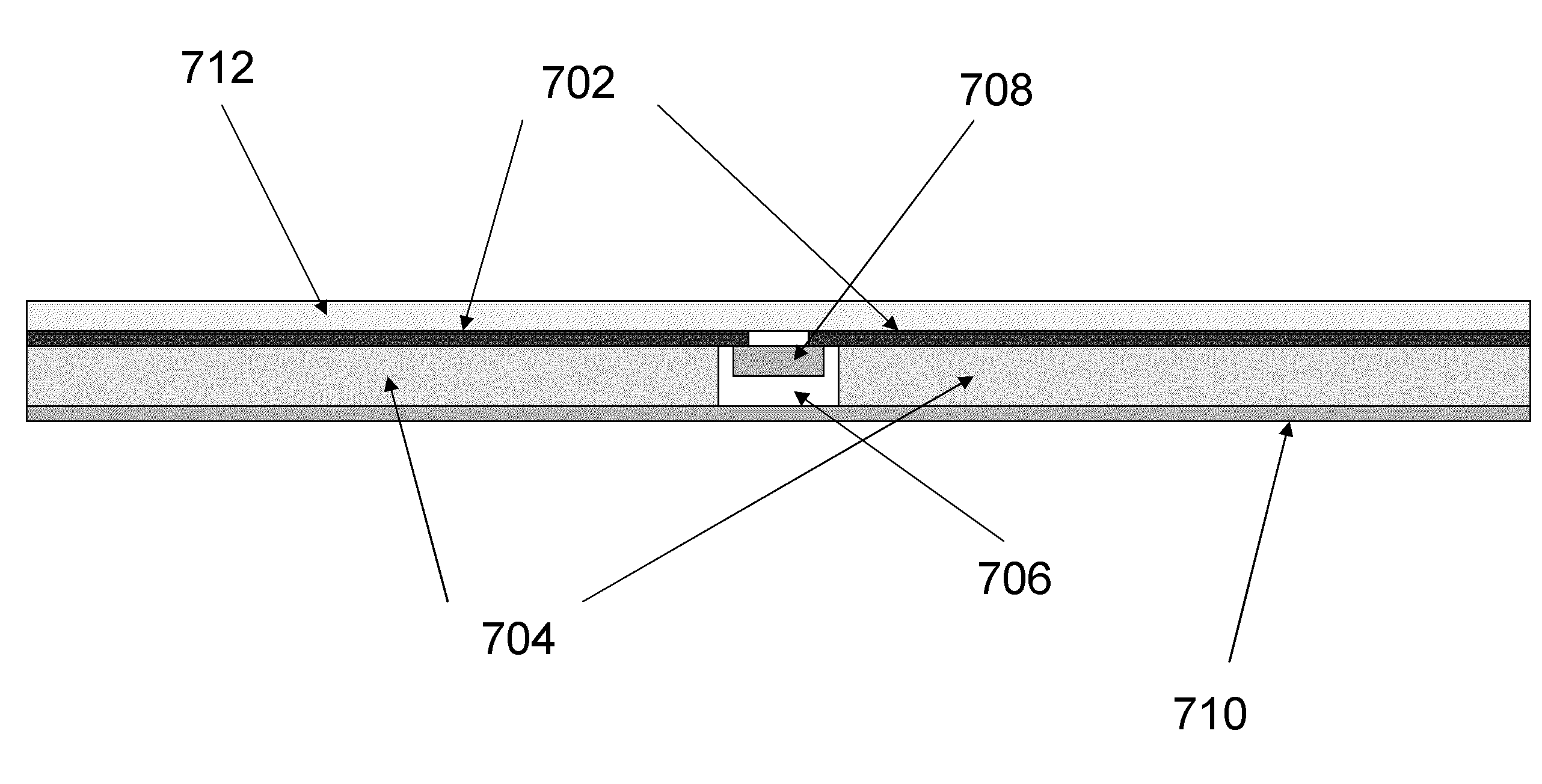
[0015]In one embodiment, photovoltaic module is disclosed. The photovoltaic module includes at least one substrate having at least one via formed therethrough and one or more circuits coupled to the at least one substrate. The circuit has a positive portion coupled to the first substrate and a negative portion coupled to the at least one substrate. The photovoltaic module also includes one or more bypass diodes coupled between the positive position and the negative portion. The photovoltaic module also includes one or more solar cells coupled to the one or more circuits.
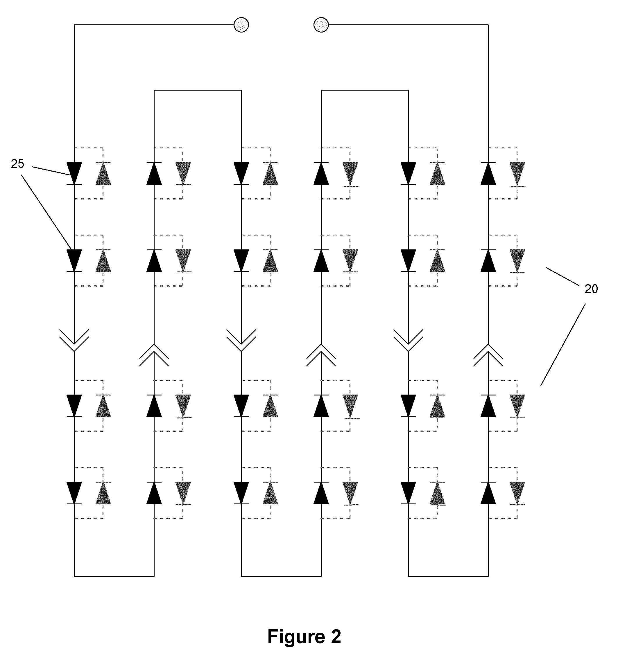
[0016]In another embodiment, a photovoltaic module is disclosed. The photovoltaic module includes at least one substrate having at least one via formed therethrough and one or more circuits coupled to the at least one substrate. The circuit has a positive portion coupled to the at least one substrate and a negative portion coupled to the at least one substrate. The photovoltaic module includes one or more active bypass elements coupled between the positive position and the negative portion and one or more solar cells coupled to the one or more circuits.
[0017]In another embodiment, a dynamic solar cell network is disclosed. The network includes a switchboard and a plurality of solar cells individually coupled to the switchboard. The switchboard is capable of dynamically optimizing power generation of the dynamic network based on the performance of each solar cell of the plurality of solar cells to optimize power generation of the plurality of solar cells.

Problems solved by technology

Nevertheless, several factors can cause the current of the solar cells to be mismatched in a module and thereby reduce the module performance in the system.
Solar cells with highly mismatched currents in series circuits also can introduce another field degradation problem due to overheating of the solar cell with the lowest current.
The issue occurs because the solar cell with the low current will be driven into reverse bias and eventually into breakdown by the other current sources (i.e., solar cells) in the electrical circuit.
In the most extreme case, the output of the entire string is lost if the electrical interconnect completely fails, or if one individual solar cell is completely shaded, in the string.
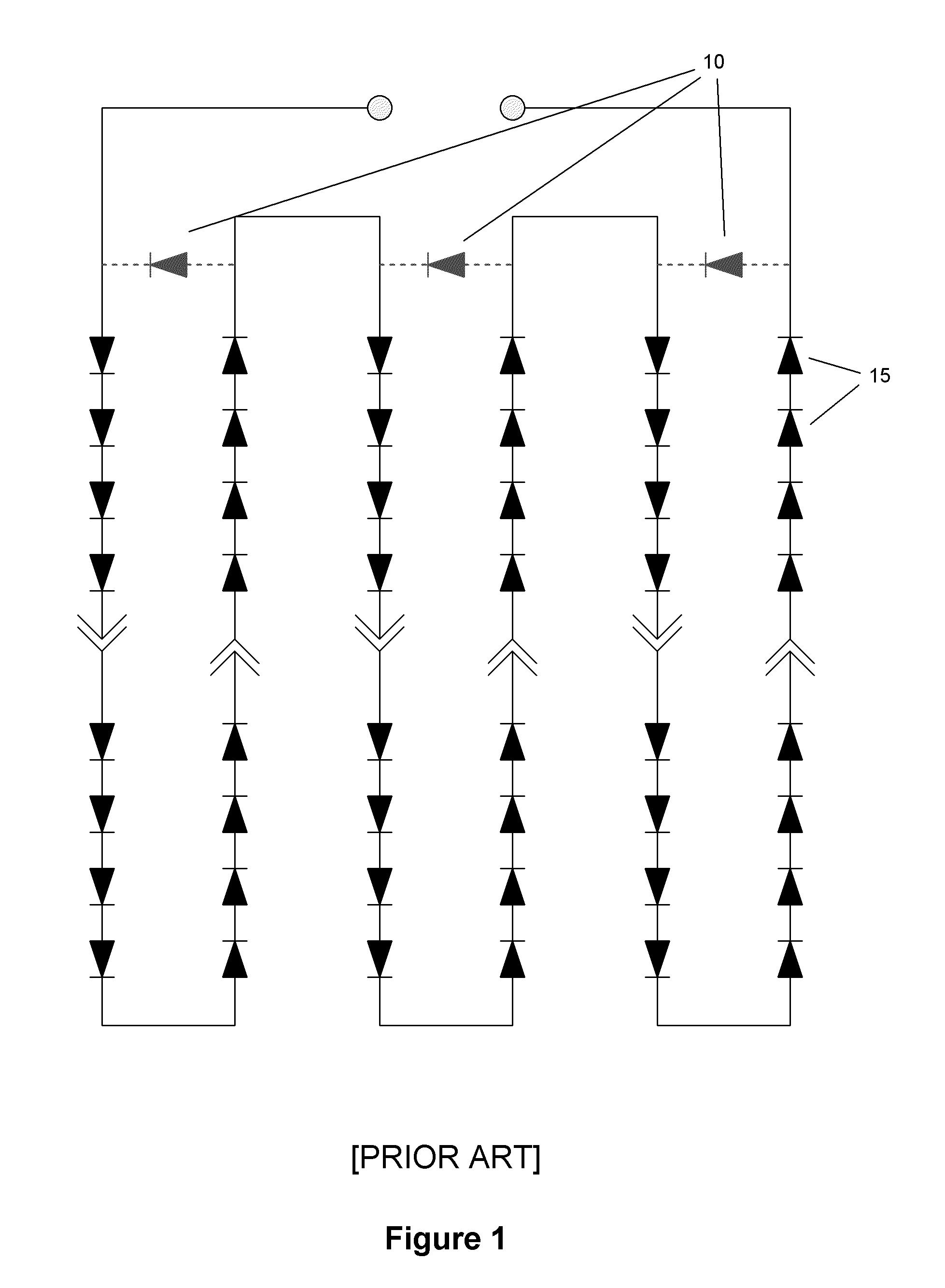
Thus, although current solar cell circuits with bypass diodes across a limited number of solar cell strings minimize the possibility of damage to the PV module, they still allow for a large performance degradation of the PV module.
In the above example, up to one third of the module output could be lost due to fault in a single solar cell.

Method used


Image

  • Integrated bypass diode assemblies for back contact solar cells and modules
  • Integrated bypass diode assemblies for back contact solar cells and modules
  • Integrated bypass diode assemblies for back contact solar cells and modules

Examples


Embodiment Construction

[0030]The present invention improves the performance of a module by minimizing the impact of non-optimal operating conditions or degradation in individual solar cells on PV module output through the use of novel solar cell circuit geometries enabled by integration with the module assembly technology. The use of back-contact cells and a module backsheet with an electrical circuit (“flexible circuit”) wherein the module electrical circuit and the module lamination are performed in a single step are described in commonly owned U.S. patent application Ser. No. 11 / 963,841, entitled “Interconnect Technologies for Back Contact Solar Cells and Modules”. Flexible circuits may comprise multiple layers with conductive paths between layers that can enable complex circuit geometries. The simplest multi-level flexible circuit has an electrical circuit on both surfaces of the substrates. Alternatively, dielectric layers can be used for isolation between conductive layers.

[0031]Most crystalline-sil...


PUM


Abstract

The present invention comprises methods for manufacturing solar cell modules having improved fault tolerance and the ability to maximize module power output in response to non-optimal operation of one or more solar cells in the module. To improve the fault tolerance, the individual solar cells may each have a bypass diode coupled thereto to that when a single solar cell faults, only the faulted solar cell is affected. In one embodiment, a transistor may be used to improve the fault tolerance of a solar cell module.

Description

CROSS-REFERENCE TO RELATED APPLICATIONS[0001]This application claims benefit of U.S. Provisional Patent Application Ser. No. 61 / 115,280, filed Nov. 17, 2008, and U.S. Provisional Patent Application Ser. No. 61 / 116,093, filed Nov. 19, 2008, both of which are herein incorporated by reference.BACKGROUND OF THE INVENTION[0002]1. Field of the Invention[0003]The present invention comprises methods for manufacturing solar cell modules having improved fault tolerance and the ability to maximize module power output in response to non-optimal operation of one or more solar cells in the module or to non-optimal operation conditions such as shading.[0004]2. Description of the Related Art[0005]Photovoltaic (PV) modules consist of solar cells that are electrically connected in various series and parallel configurations and encapsulated for environmental protection. Usually, the solar cells are electrically connected in series. A series rather than parallel electrical circuit produces a higher vol...

Claims


Application Information

Patent Timeline
Patent Type & Authority Applications(United States)
IPC IPC(8): H01L31/042H01L31/00
CPCY02E10/50H01L31/0443
Inventor GEE, JAMESMEAKIN, DAVID H.BAGH, FARES
Owner APPLIED MATERIALS INC
Learn More