Air barrier for datacenter usage which automatically retracts when fire sprinklers are activated

a technology of air barrier and datacenter, which is applied in the direction of curtain suspension device, door/window protective device, door/window, etc., and can solve the problem of manpower approach that is obviously unacceptabl

Inactive Publication Date: 2010-05-06
IBM CORP
View PDF6 Cites 26 Cited by
  • Summary
  • Abstract
  • Description
  • Claims
  • Application Information

AI Technical Summary

Benefits of technology

[0007]Accordingly, pursuant to the present invention, in order to obtain the desired functions in separating the air flows between the hot-air and cold-air aisles, of the computer racks, there are provided suitable barriers which will permit fire sprinklers to operate efficiently in quenching fires or conflagrations which may be encountered in the datacenters without such barriers creating obstructions.

Problems solved by technology

Such a manual approach is obviously unacceptable in a datacenter, where automatic retraction of the barrier must be triggered by activation of the fire sprinklers.

Method used


Image

  • Air barrier for datacenter usage which automatically retracts when fire sprinklers are activated
  • Air barrier for datacenter usage which automatically retracts when fire sprinklers are activated

Examples


Embodiment Construction

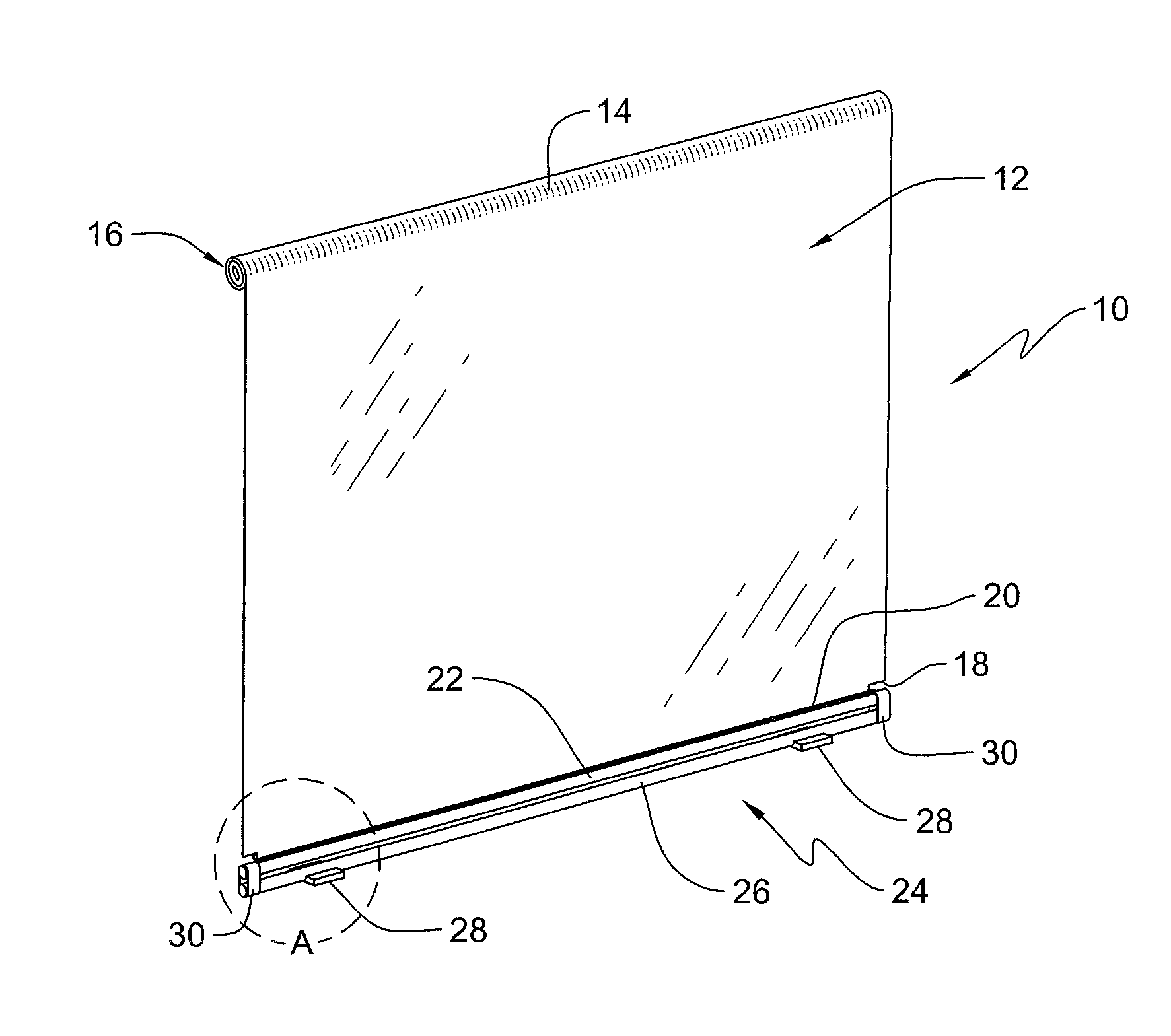
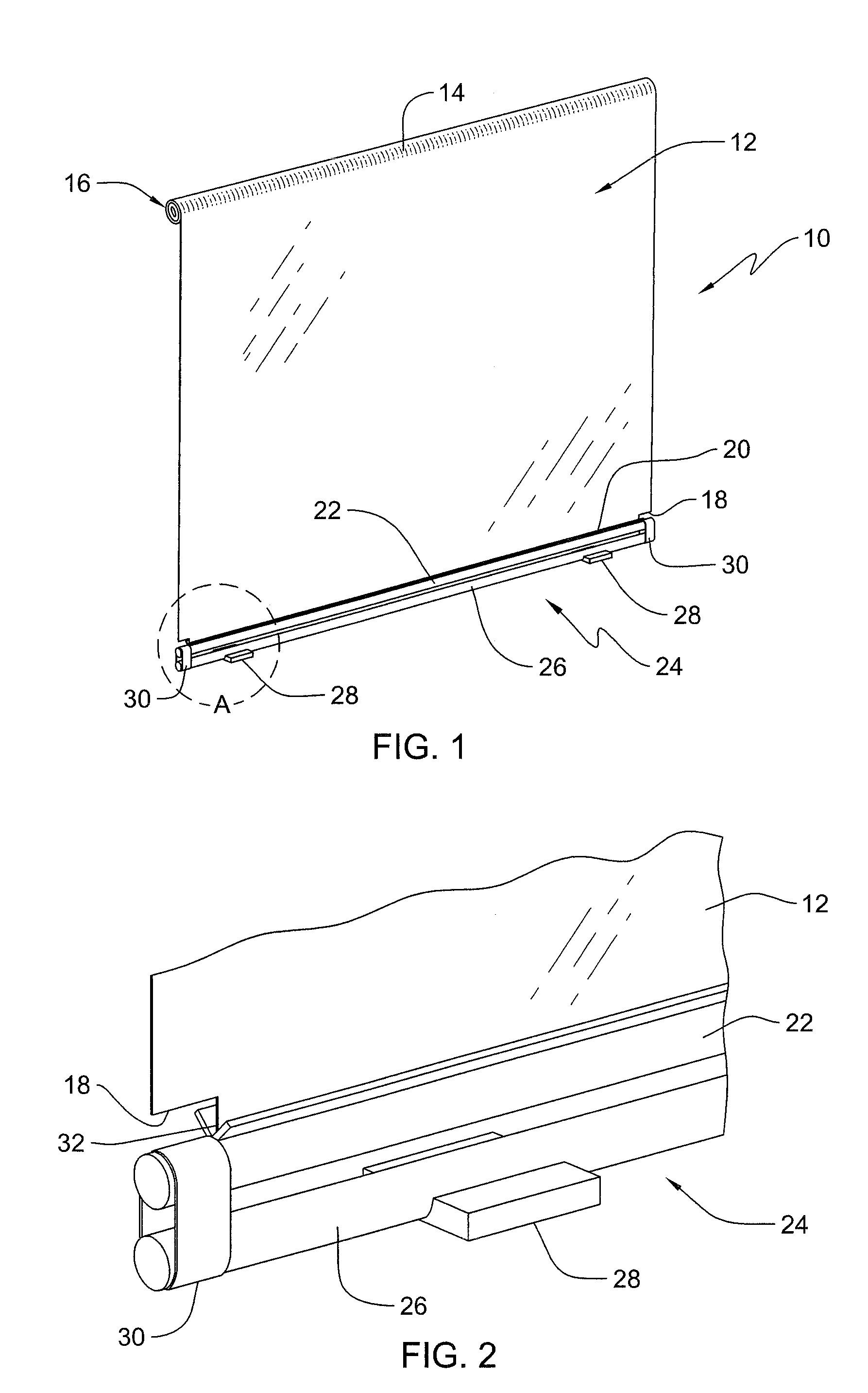
[0015]Referring, in particularity to the drawings, FIG. 1 illustrates a barrier structure 10 which is generally in the shape of a curtain-like roll-up shade. The barrier structure has the shade portion 12 constituted of an airflow-resistant or impervious material, which may be of a fabric or other flexible consistency. The shade portion 12 may be opaque, translucent or transparent in nature.

[0016]At the upper end 14 of the barrier structure, there is a spring-loaded roller 16, which has the upper end of shade portion 12 attached thereto, and wherein the roller 16 is adapted to be fastened to a suspended ceiling of a datacenter (not shown), or to any other ceiling structure located above the upper end or end surfaces of computer racks (not shown) in a spaced relationship with the ceiling. The roller 16 is fastened to the ceiling so as to be freely rotatably about its longitudinal axis, and normally imparts a roll-up winding force to the shade portion 12 about the roller for retractin...


PUM


Abstract

An air barrier structure located in an airflow passageway for datacenter usage, which is automatically retractable upon activation of fire sprinklers in the event of a conflagration. The barrier structure is a shade-type roll up member, which in the absence of any complex mechanical structure, will automatically retract about a spring-loaded roller upon the activation of a fire sprinkler, and whereby the barrier incorporates water-soluble structural aspects which will facilitate such automatic retraction upon being impinged upon and dissolved by a flow of water emanating from the fire sprinkler.

Description

BACKGROUND OF THE INVENTION[0001]1. Field of the Invention[0002]The present invention relates to an air barrier structure located in an air flow passageway for datacenter usage, which is automatically retractable upon activation of fire sprinklers in the event of a conflagration.[0003]In the present state of the data processing technology, large datacenters are employed, which require the consumption of huge amounts of electricity, and thereby frequently necessitate that extensive amounts of air be conveyed across computer racks of such datacenters in order to conduct heat that is generated by the electronic components in the computer racks to computer room air conditioner units (CRAC), or to other suitable air cooling arrangements.[0004]2. Discussion of the Prior Art[0005]A problem which is frequently encountered in such datacenter installations is an undesirable mixing of flows of air of widely divergent temperatures emanating from hot-air aisles and from cold-air aisles between t...

Claims


Application Information

Patent Timeline
Patent Type & Authority Applications(United States)
IPC IPC(8): A47G5/02
CPCA62C3/16E06B9/42E06B2009/585
Inventor KARIDIS, JOHN P.
Owner IBM CORP
Why Eureka
Try Eureka