Dual rotor helicopter with tilted rotational axes

Active Publication Date: 2010-05-06
ZENON DRAGAN
View PDF7 Cites 139 Cited by
  • Summary
  • Abstract
  • Description
  • Claims
  • Application Information

AI Technical Summary

Benefits of technology

[0010]The invention provides, in a first embodiment, a rotary wing aircraft apparatus comprising a body and a rotor pair connected to the body by an arm. The rotor pair comprising an upper rotor driven by an upper motor and rotating about an upper rotor axis and a lower rotor driven by a lower motor and rotating about a lower rotor axis. The upper and lower rotor axes are tilted with respect to each other. Tilting the axes away from the arm increases the distance from the rotor blades to the arm, and decreases the risk of the blades of the rotor contacting the arm.
[0011]The invention provides, in a second embodiment,

Problems solved by technology

Tilting the axes away from the arm increases the distance from the rotor blades

Method used


Image

  • Dual rotor helicopter with tilted rotational axes
  • Dual rotor helicopter with tilted rotational axes
  • Dual rotor helicopter with tilted rotational axes

Examples


Embodiment Construction

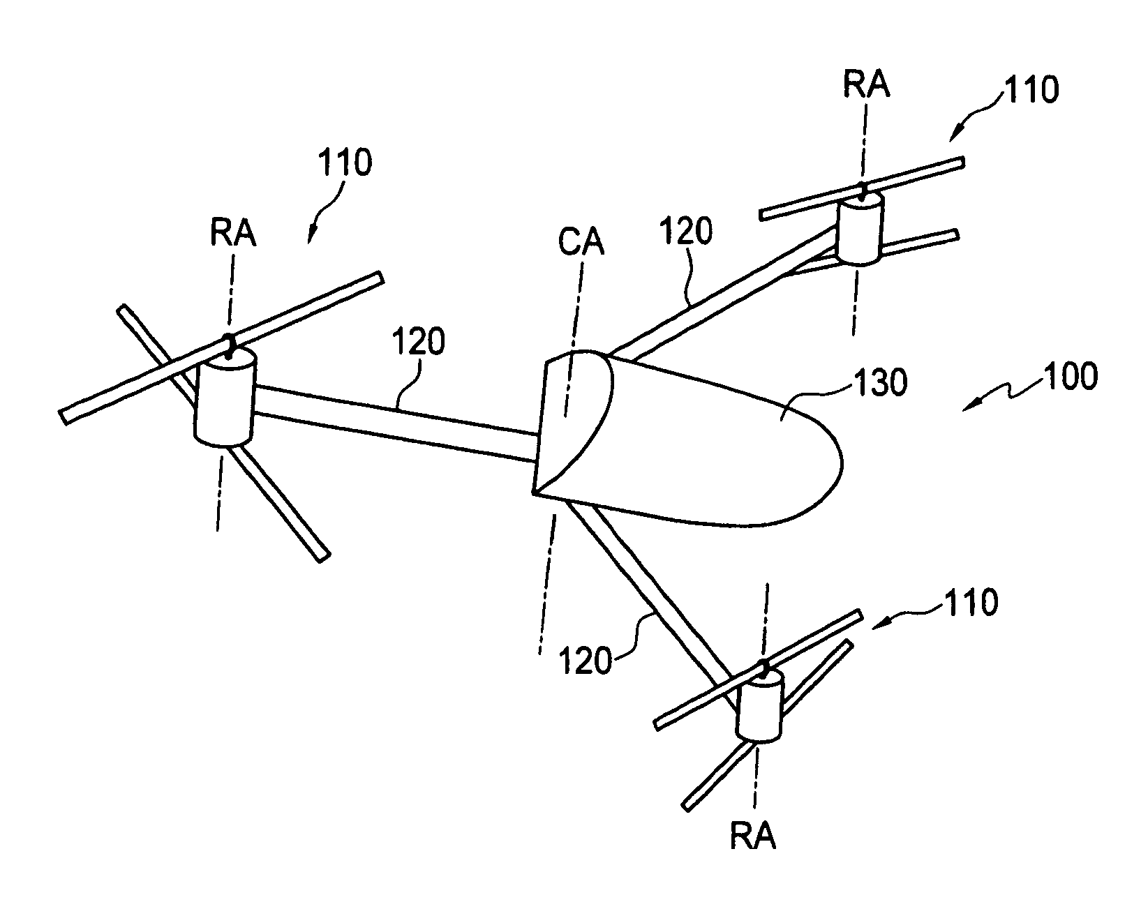
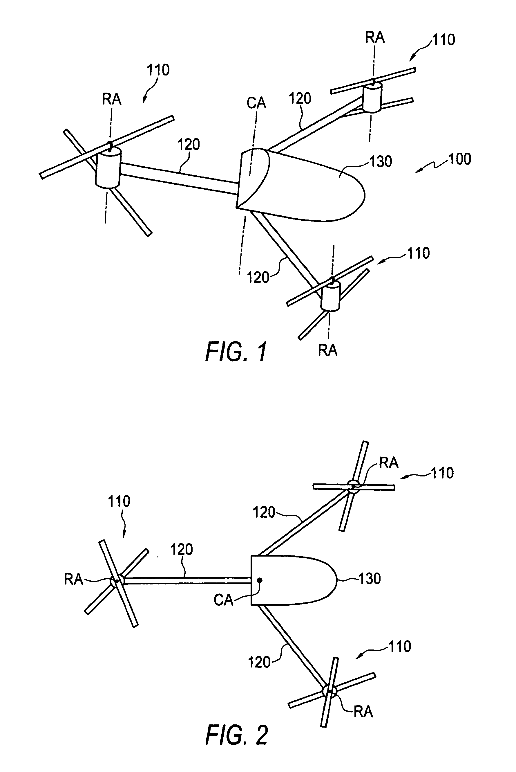
[0030]FIGS. 1 and 2 illustrate an aircraft 100 with three coaxial rotor pairs 110. Using the three coaxial rotor pairs 110, aircraft 100 is capable of performing the maneuvers a typical conventional helicopter is capable of, yet does not require the mechanical complexity of a typical conventional helicopter and all of the coaxial rotor pairs 110 can be used to create lift.

[0031]Each of the rotor pairs 110 are positioned at the end of an arm 120 connected to a main body 130 of the aircraft 100. In an aspect, the arms 120 are positioned extending at regular intervals around a central axis, CA, with each arm 120 positioning the rotor pair 110 attached to the end of the arm 120 the same distance away from the central axis, CA, as the other rotor pairs 110 and with each arm 120 positioned so the rotor pairs 110 are positioned at the corners of an equilateral triangle, as illustrated in the top view of FIG. 2.

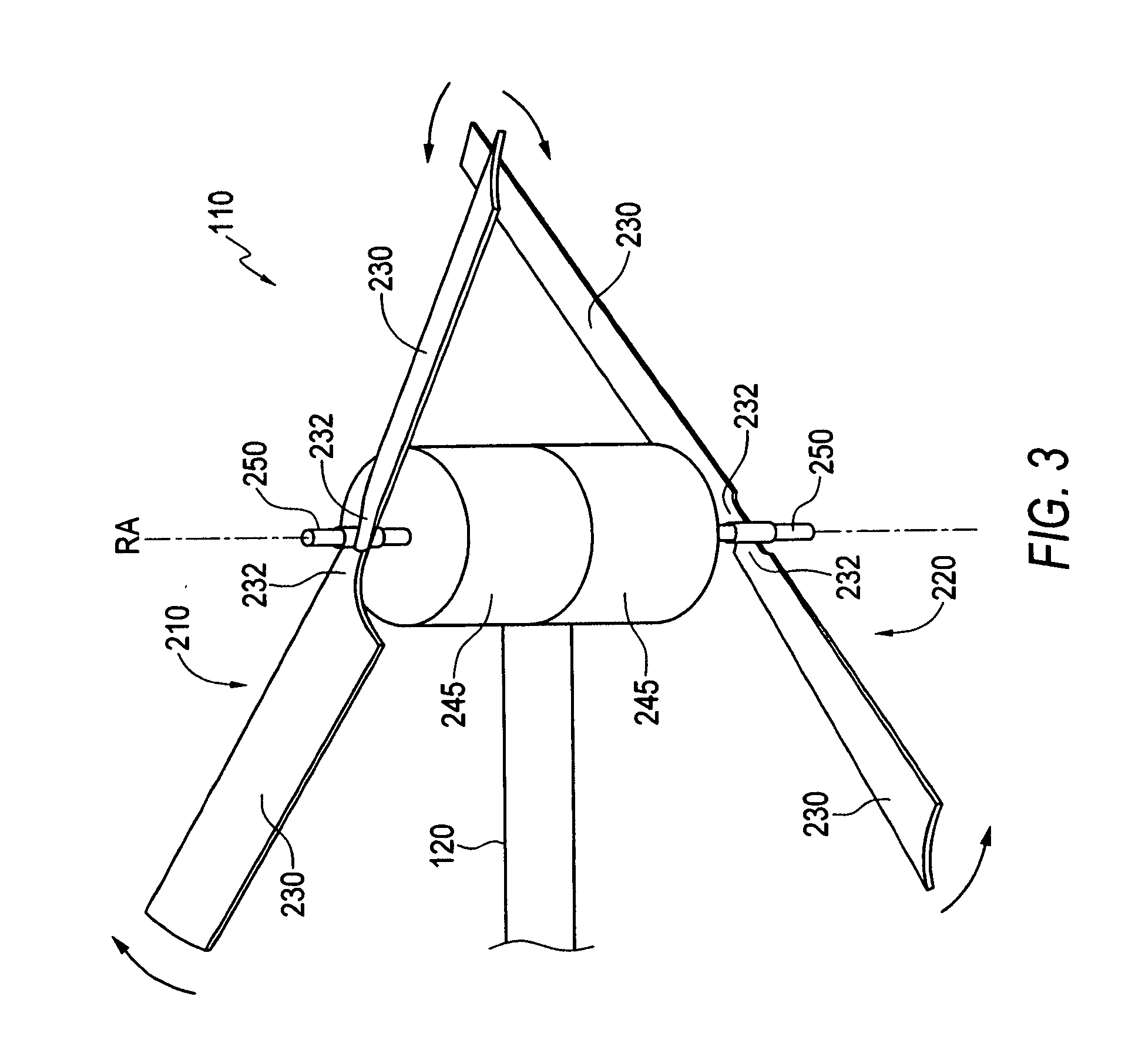
[0032]FIG. 3 illustrates a perspective view of one of the rotor pairs 110. The r...


PUM


Abstract

A rotary wing aircraft apparatus includes a body and a rotor pair connected to the body by an arm. The rotor pair has an upper rotor driven by an upper motor and rotating about an upper rotor axis and a lower rotor driven by a lower motor and rotating about a lower rotor axis. The upper and lower rotor axes are tilted with respect to each other. Tilting the axes away from the arm increases the distance from the rotor blades to the arm, and decreases the risk of the blades of the rotor contacting the arm. In an aircraft with a plurality of arms extending from the body, and a rotor assembly connected to each arm, the arms can be pivoted from a flying position, where the arms extend laterally outward to a folded position where the arms are positioned substantially parallel and adjacent to each other.

Description

[0001]This invention is in the field of rotary wing aircrafts or helicopters and more particularly rotary wing aircrafts with upper and lower rotors.BACKGROUND[0002]Helicopters using horizontal rotors have been known for a long time. They allow an aircraft to move vertically (allowing vertical take-offs), hover in the air, move side to side, etc. The use of horizontal rotors gives helicopters an unprecedented amount of movement in relation to a fixed wing craft.[0003]However, conventional helicopters are typically very complex. Most conventional helicopters use a large horizontal rotor for lift and a smaller vertical rotor (the tail rotor) to counterbalance torque imposed on the helicopter by the rotation of the large lift rotor. By altering the pitch of the blades of the small vertical rotor, the entire helicopter can be pivoted from side to side or held straight.[0004]The horizontal rotor must also be specially designed to cause the helicopter to tilt in different directions when ...

Claims


Application Information

Patent Timeline
IPC IPC(8): B64C27/08
CPCB64C39/024B64C2201/027B64C2201/108B64U10/13B64U30/20
Inventor OLM, ORVILLEWOOD, GREGDRAGAN, ZENON
Owner ZENON DRAGAN
Why Eureka
Try Eureka